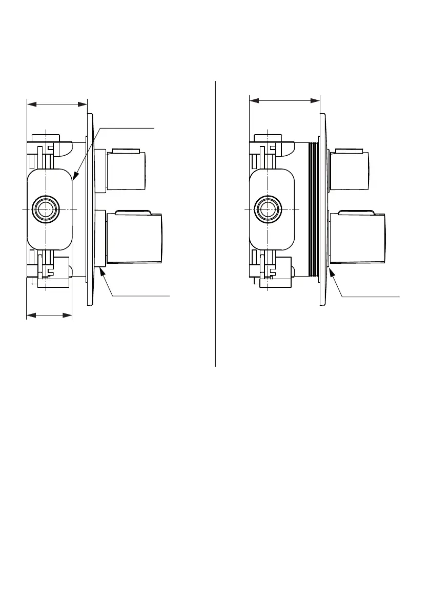
4.2 Kit-1 mounting depth control cont’
Effectively, the escutcheon plate can oat 10mm, between the MIN & MAX (markers on the valve-box) thus
permitting the mounting depth to vary by 10mm.
44
58 Min
68 Max
Valve-box
shoulder
Min shroud
exposure
Max shroud
exposure
Cosmetically, when the escutcheon plate is
furthest back (valve-box trimmed at MIN), this
exposes more of the shroud diameters under
the handle.
Conversely, when the escutcheon plate is
furthest forward (valve-box trimmed at MAX),
the shroud diameters under the handle are
hardly noticeable.
Valve-box shoulder
The valve-box shoulders are created by the bosses surrounding the ports of the valve.
For example, if the valve-box is being panel mounted, the large diameter of the valve-box will pass through
a hole in the panel & eventually stop against these shoulders.
See 5.7 for an example of how these shoulders can be used as a stop face.
9
 Loading...