25
INTERNAL WIRING
26
EXTERNAL ELECTRICAL CONTROLS
Wiring External to the Boiler
The fuse rating should be 3A.
Wiring external to the boiler MUST be in accordance with the current I.E.E.
(BS.7671) Wiring Regulations and any local regulations.
Frost Protection
If parts of the pipework run outside the house or if the boiler will be left off for
more than a day or so then a frost thermostat should be wired into the system.
The frost thermostat should be sited in a cold place but where it can sense heat
from the system.
Note. If the boiler is installed in a garage it may be necessary to t a pipe
thermostat, preferably on the return pipework.
A mains cable must be connected to a permanent live supply and NOT switched by
thermostats/programmers. To do so follow the instructions below:
1. Remove the front panel. Refer to Frame 39.
2. Swing the control box down into the service position. Refer to frame 45.
3. Route cable through the cable clamp and grommet and tighten to provide cord anchorage.
4. Connect the live, neutral and earth wires to the terminal strip. When making the mains
electrical connections to the boiler it is important that the wires are prepared in such a
way that the earth conductor is longer than the current carrying conductors, such that if
the cord anchorage should slip, the current carrying conductors become taut before the
earthing conductor.
5. Swing the control box back up into the operating position and re-t the front panel
ensuring a good seal is made.
3G9989
N
L
N
FROST
STAT
(
OPTIONAL)
ROOM
STAT/
TIMER
Room
Stat or
Prog.
Room
Stat
Optional
Frost Stat
Earths are not shown for clarity but must
never be omitted.
24
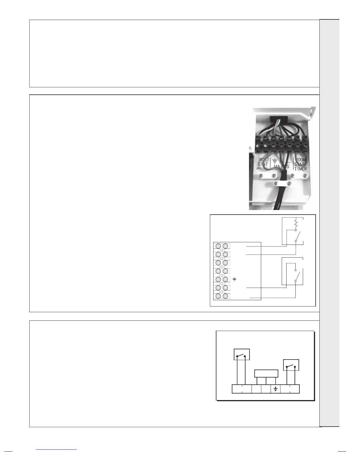
ELECTRICAL CONNECTIONS
Wiring should be 3 core PVC insulated cable, not less than
0.75mm
2
(24 x 0.2mm), and to BS 6500 Table 16. For IE
reference should be made to the current ETCI rules for electrical
installations.
Connection must be made in a way that allows complete isolation
of the electrical supply such as a double pole switch having
a 3mm (1/8”) contact separation in both poles. The means of
isolation must be accessible to the user after installation.
WARNING. This appliance MUST be earthed.
A mains supply of 230Vac ~ 50 Hz is required.
The fuse rating should be 3A. All external controls and wiring
must be suitable for mains voltage.
Wiring external to the boiler MUST be in accordance with the
current I.E.E. (BS.7671) Wiring Regulations and any local
regulations.
The Independent boiler comes pre-tted with a link wire between the room
thermostat/Timer connections on the terminal strip. This creates a permanent
call for heat and must be removed when adding a room thermostat.
ROOM THERMOSTAT - WIRING
1. Remove link wire between Room stat/timer terminals.
2. Connect room stat as shown in wiring diagram opposite.
3. If room stat has a neutral connection, connect this to terminal N (load) in
the fused spur.
FROST THERMOSTAT - WIRING
If parts of the system are vulnerable to freezing or the programmer is likely to
be left off during cold weather, a frost stat should be tted in conjunction with a
pipe thermostat.
1. Position the frost thermostat in a suitable position, i.e. area vulnerable to
freezing.
2. Connect frost stat across terminals marked frost stat as shown in wiring
diagram opposite.