1. Refer to Frame 40.
2. Drain down the boiler. Refer to Frame 55.
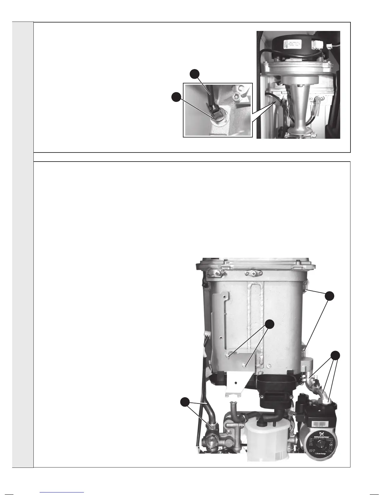
3. Unplug the electrical lead.
4. Unscrew the thermistor (to facilitate removal a
13mm socket spanner should be used).
5. Fit the new thermistor using the sealing washer
provided.
6. Reassemble in the reverse order.
7. Rell the boiler.
8. Check the operation of the boiler. Refer to Frames
29 & 30.
65
NO FLOW THERMISTOR REPLACEMENT
4
3
66
HEAT ENGINE RENEWAL
Refer also to Frame 5 - ‘Boiler Exploded View’
IMPORTANT
Before starting the removal procedure, protect the gas and electrical controls with a waterproof sheet or plastic bag.
1. Refer to Frame 40.
2. Drain the boiler. Refer to Frame 55.
3. Remove the fan / venturi assembly and place on one
side. Refer to Frame 41.
4. Remove the burner and place on one side. Refer to
Frame 43.
5. Remove the ignition and detection electrodes and
divertor actuator head. Refer to Frames 45, 46 and
49.
6. Remove the spark generator. Refer to Frame 47.
7. Remove the gas valve. Refer to Frame 48.
8. Remove the expansion vessel. Refer to Frame 67.
9. Remove the ow thermistor. Refer to Frame 65.
10. Remove the 2 M5 screws retaining the gas valve
mounting bracket and transfer bracket to the new
heat exchanger.
11. Undo the inlet pipe union nut and remove the
retaining spring clip and remove pipe.
12. Undo the ow pipe union nut and remove pipe.
13. Remove the condensate rubber pipe. Refer to Frame
50, no. 2.
14. Remove the two heat exchanger xing screws.
15. Remove the Heat exchanger slide out of location
bracket.
16. Reassemble in reverse order, ensuring the heat
exchanger LH retaining bracket is correctly
positioned. Replace any new ‘o’ rings supplied with
new heat exchanger and replacing gaskets or seals
if any sign of damage is evident. When replacing the
spring clips located on the return pipe connection,
ensure clip is oriented to correctly match connecting
pipe diameters.
14
11
10
12
17. Ensure the trap/siphon is lled with water. Refer to Frame 50.
18. Rell the boiler.
19. Check operation of the boiler. Refer to Frames 29 & 30.
SERVICING