57
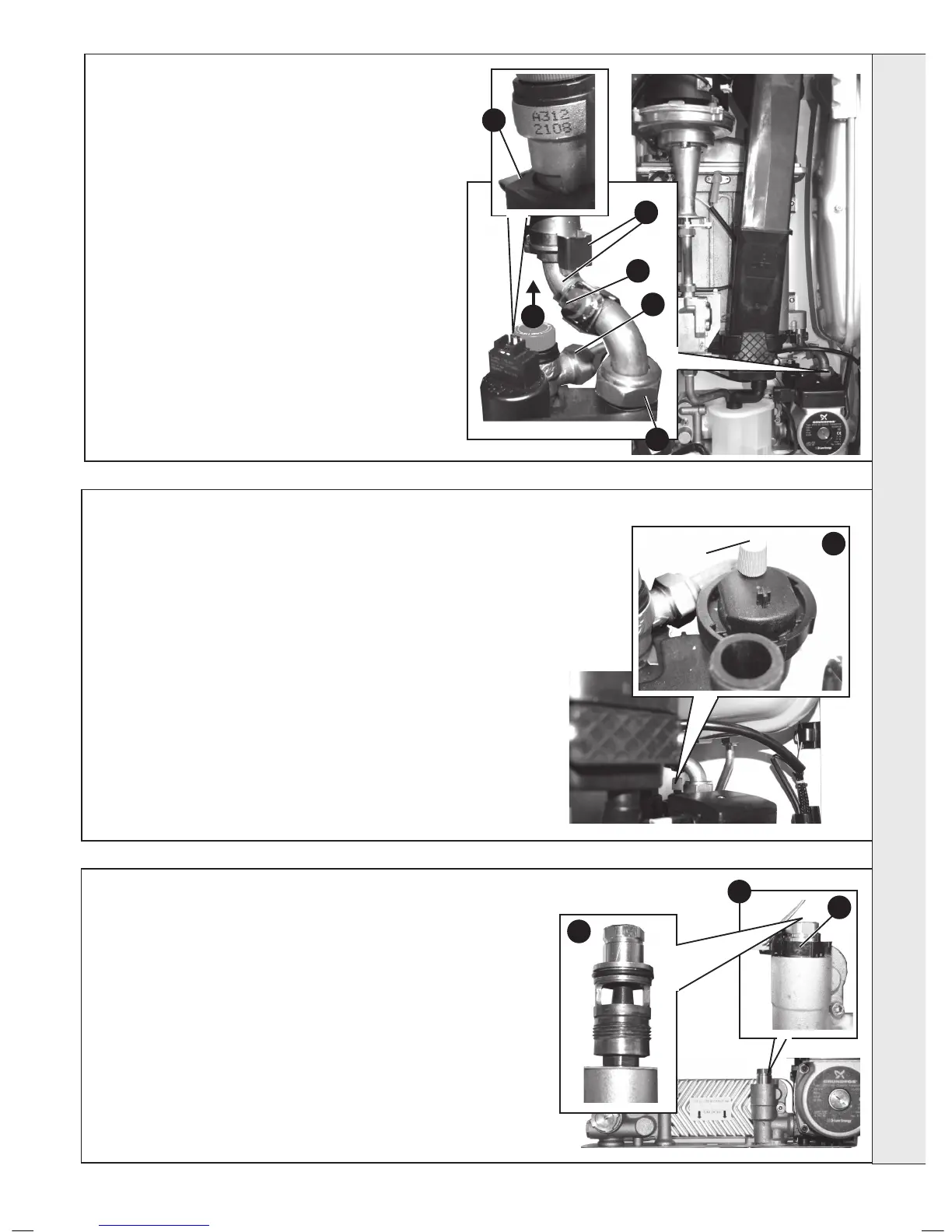
SAFETY RELIEF VALVE RENEWAL
1. Refer to Frame 40.
2. Drain the boiler. Refer to Frame 55.
3. Remove condensate trap/siphon. Refer to Frame 50.
4. Remove expansion vessel. Refer to Frame 67.
5. Disconnect electrical connection from return thermistor.
6. Disconnect 22mm pipe connection at rear of pump
outlet.
7. Pull off clip retaining the pipe to the heat exchanger.
Swing pipe to clear the pump and remove pipe.
8. Undo safety valve union connection.
9. Withdraw clip securing the safety valve.
10. Lift safety valve from boiler.
11. Fit new safety valve and reassemble in reverse order
ensuring new ‘o’ ring is tted to the top of return pipe.
12. Rell boiler. Check operation of boiler. Refer to Frames
29 & 30.
58
PUMP AUTOMATIC AIR VENT REPLACEMENT
1. Refer to Frame 40.
2. Drain the boiler. Refer to frame 55.
3. Remove the expansion vessel. Refer to Frame 67.
4. Firstly, increase access area by disconnecting the 22mm pipe connection
at top of pump chamber and bottom of heat exchanger and remove pipe
Refer to Frame 57.
5. The automatic air vent head is retained in the pump body with a bayonet
connection. The air vent head and oat assembly is removed by turning
the head anti-clockwise (viewed from above) and pulling upwards.
6. Reassembly is the reverse of the above. Ensure the air vent head ‘o’ ring
seal is in place when retting and the new ‘o’ ring is tted to the return pipe
top connection.
7. Ensure the air vent cap is loose.
8. Rell the boiler. Check for leaks around the new air vent joint.
9. Check the operation of the boiler. Refer to Frames 29 & 30.
5
6
7
5
8
9
10
Dust Cap
4
59
DHW FLOW TURBINE CARTRIDGE REPLACEMENT
1. Refer to Frame 40.
2. Drain the boiler. Refer to Frame 55.
3. Remove condensate trap/siphon. Refer to Frame 50.
4. Remove the DHW ow turbine sensor. Refer to Frame 54.
5. Unscrew the top connection to access the internal part.
6. Fit the new turbine cartridge.
7. Ret the turbine ow sensor
8. Reassemble in reverse order.
9. Rell the boiler.
10. Check operation of the boiler. Refer to Frames 29 & 30.
5
7
SERVICING