33
SERVICING SCHEDULE
For the very latest copy of literature for specication & maintenance practices, visit our website www.idealboilers.com, where you
will be able to download the relevant information. N.B. Technical Bulletins are also available on www.idealboilers.com.
WARNING. Always turn OFF the gas supply at the gas service cock, and switch OFF and disconnect the electricity
supply to the appliance before servicing.
Combustion testing must be carried out by a competent person using a combustion analyser conforming to BS7927.
To ensure the continued safe and efcient operation of the appliance it is recommended that it is checked at regular intervals and
serviced as necessary. The frequency of servicing will depend upon the installation condition and usage but should be carried out
at least annually.
It is the law that any service work must be carried out by a Gas Safe Registered Engineer. In IE service work must be carried out
by a Registered Gas Installer (RGII).
INSPECTION
1. Light the boiler and carry out a pre-service check, noting any
operational faults.
2. Check the ue terminal (and terminal guard if tted) is undamaged
and clear of any obstruction.
3. Check all water and gas joints for signs of leakage. Remake any
suspect joints ensuring a gas tightness check is carried out if
applicable and the water system is correctly relled, vented and
re-pressurised.
CLEANING PROCEDURE
Note. In order to carry out either servicing or replacement of
components the boiler front panel must be removed. Refer to
Frame 34.
1. Clean the main burner. Refer to frame 36.
2. Clean the heat exchanger & condensate trap/siphon. Refer to
Frames 38 & 37.
3. Check the main injector for blockage or damage. Refer to Frame
42.
4. Check that the ue terminal is unobstructed and that the ue system
is sealed correctly.
ALSO IF THE DHW FLOW RATE IS IN QUESTION :-
5. Check the DHW lter for blockage. Refer to Frame 64.
The cleaning procedures are covered more fully in Frames 34-39 and
MUST be carried out in sequence.
IMPORTANT.
6. After completing the servicing or exchange of components always
test for gas tightness.
7. When work is complete the front panel MUST be correctly retted,
ensuring that a good seal is made.
Do NOT OPERATE the boiler if the front panel is not
tted.
8. If, for any reason, the condensate trap/siphon has been removed
ensure the trap is relled with water before
reassembling.
9. Check the gas consumption.
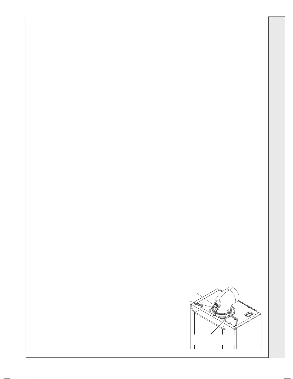
10. Check combustion by connecting the ue gas analyser to the ue
gas sampling point as shown in the diagram and measure CO &
CO
2
.
If the CO/CO
2
ratio is greater than 0.004 AND the integrity of the
complete ue system and combustion circuit seals have been
veried and the inlet gas pressure (and gas rate) have been
veried, then contact Ideal.
11. Complete the service section in the Benchmark Commissioning
Checklist.
GENERAL
Please Note: During routine servicing, and after any
maintenance or change of part of the combustion
circuit, the following must be checked:
- The integrity of the ue system and the ue seals,
- The integrity of the boiler combustion circuit and
the relevant seals
- The operational (working) gas inlet pressure at
maximum rate.
- The gas rate
- The combustion performance.
COMPETENCE TO CARRY OUT THE CHECK
OF COMBUSTION PERFORMANCE
Please Note: BS 6798:2009 Specication for
installation and maintenance of gas-red boilers of
rated input not exceeding 70kW net advises that:
- The person carrying out a combustion
measurement should have been assessed as
competent in the use of a ue gas analyser and the
interpretation of the results.
- The ue gas analyser used should be one meeting
the requirements of BS7927 or BS-EN50379-3
and be calibrated in accordance with the analyser
manufacturers requirements, and
- Competence can be demonstrated by satisfactory
completion of the CPA1 ACS assessment, which
covers the use of electronic portable combustion
gas analysers in accordance with BS7967, Parts 1
to 4.
SERVICING