60
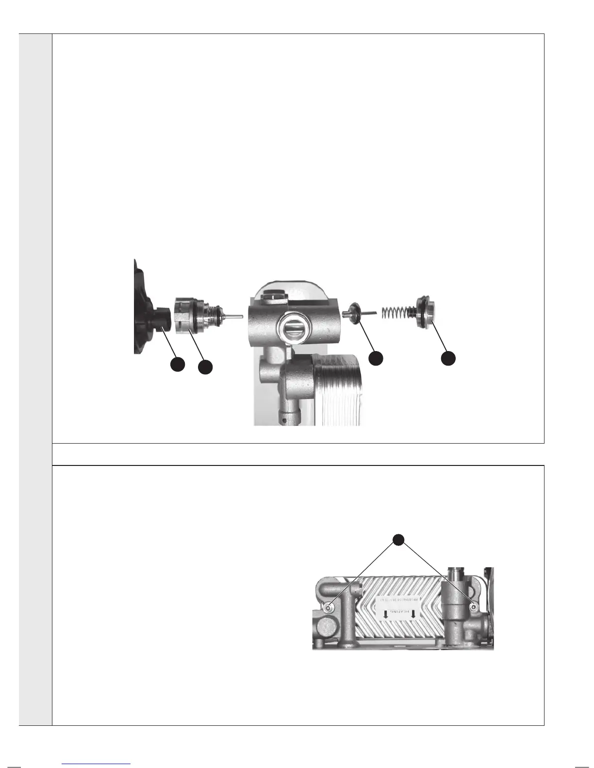
DIVERTER VALVE INTERNAL CARTRIDGE REPLACEMENT
FRONT CARTRIDGE REPLACEMENT
1. Refer to Frame 40.
2. Drain the boiler. Refer to Frame 55.
3. Remove the diverter valve head. Refer
to Frame 49.
4. Unscrew the top connection to access
the internal cartridge.
5. Fit the new valve mechanism ensuring
the correct t of the pin.
6. Reassemble in reverse order.
7. Rell the boiler.
8. Check operation of the boiler. Refer to
Frames 29 & 30.
REAR CARTRIDGE REPLACEMENT
1. Refer to Frame 40.
2. Drain the boiler. Refer to Frame 55.
3. Remove the diverter valve head. Refer to Frame 49.
4. Remove the ow pipe. Refer to Frame 66 no. 12.
5. Disconnect the CH ow pipe and DHW outlet pipe union connections underneath
the boiler. Refer to Frame 55.
6. Remove the plate heat exchanger LH xing screw. Refer to Frame 61.
7. Remove the screw retaining the brass block to the bottom of the boiler casing
and lift the brass block clear of the boiler.
8. Unscrew the rear cartridge connection.
9. Fit the new valve mechanism ensuring the correct t of the pin.
10. Reassemble in reverse order.
11. Rell the boiler.
12. Check operation of the boiler. Refer to Frames 29 & 30.
FRONT CARTRIDGE REAR CARTRIDGE
3
4
9 8
1. Refer to Frame 40.
2. Drain the boiler. Refer to Frame 55.
3. Remove condensate trap/siphon. Refer to Frame
50.
4. Remove the diverter valve actuator. Refer to
Frame 49.
5. Remove the 2 allen screws securing the plate
heat exchanger to the brass housings.
6. Manoeuvre the plate heat exchanger out of the
top LH or centre of the controls area.
7. Fit the new plate heat exchanger, using the new
o-rings supplied.
Note. The mounting pins are offset so the correct
position can be dened from the location of the
holes on the brass mounting.
8. Reassemble in reverse order.
9. Rell the boiler.
10. Check operation of the boiler. Refer to Frames 29
& 30.
61
DHW PLATE HEAT EXCHANGER REPLACEMENT
5
SERVICING