4
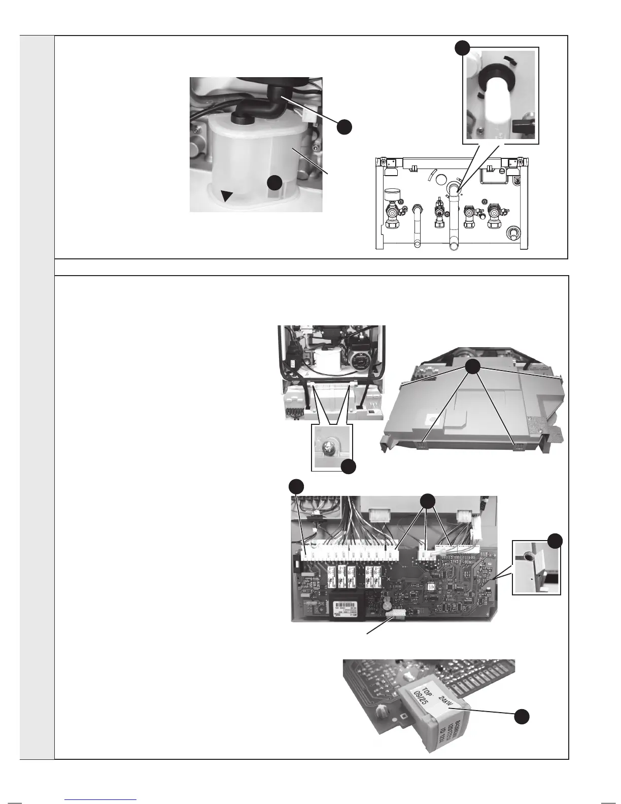
1. Refer to Frame 40.
Note: Ensure condensate trap
is fully drained before removal.
2. Pull off the rubber pipe at
the sump drain.
3. Disconnect the condensate
drain pipe.
4. Turn the siphon clockwise
to disengage and lift to
remove.
5. Reassemble in reverse
order.
6. When reassembling ensure
the trap is full of water.
7. Check operation of the boiler. Refer to Frames 29 & 30.
50
CONDENSATE TRAP/SIPHON REPLACEMENT
51
MAIN PCB REPLACEMENT
* Note. that production boiler PCB’s are factory pre-
set to operate for boiler range and output, but when
ordering Primary PCB as a spare, an additional Boiler
Chip Card (BCC) MUST also be purchased for your
specic boiler range and output.
Note. Fit the earth strap provided with the PCB to
your wrist and secure to a suitable earth on the boiler
chassis.
1. Refer to Frame 40.
2. Note the control knob positions.
3. Remove the 2 screws retaining the control box
cover.
4. Carefully lift the 4 retaining clips and remove control
box cover.
5. Unplug all lead connections to the PCB including
the ribbon cable (to facilitate ribbon cable removal,
ease side clips apart and pull upwards), also where
applicable, push the small plastic clip with an
electrical screwdriver to facilitate plug removal.
6. Spring out the two side retaining clips and pull the
PCB upwards to clear the 4 corner retaining posts.
7. Take the new Primary PCB and attach the
appropriate Boiler Chip Card (BCC) to it (this should
correspond to the output of the boiler: 24kW, 30kW
or 35kW). Note. Ensure the correct orientation
of BCC by placing “TOP” side up as shown.
8. Re-connect all plug connections.
9. Reassemble in reverse order.
10. a. Turn power on
b. Displays “8” blue light on/off, “rst digit input”,
“second digit input”, “1st letter appliance type”,
i.e. “2”, “4”, “c”
c. Move knob to required setting (standby, summer,
winter)
Note. If no BCC tted on non programmed
board items a & b will be displayed then “Boiler Type
Card Fault - Contact Installer” The correct BCC for
this appliance will need to be tted.
11.
Check operation of the boiler. Refer to Frames 29 & 30.
3
3
6
5
2
Siphon
4
Ribbon Cable Connection
7
Plastic
Clip
5
SERVICING