35
xtra
- Installation & Servicing
SERVICING
46
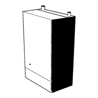
REMOVAL OF FAN / VENTURI INSPECTION
47
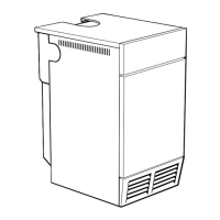
REMOVAL OF BURNER MANIFOLD
1. Refer to Frame 42.
2. Refer to Frame 46 for removal of fan/venturi
assembly.
3. Disconnect the ignition and earth lead from the
electrodes.
4. Whilst providing temporary support for the burner
manifold remove the 4 retaining nuts.
5. Withdraw the burner manifold from the boiler taking
care not to damage the electrodes.
6. Re-assemble in reverse order, replacing any seals/
gaskets which show signs of wear. The nyloc nuts
should be renewed. Ensure the short earth lead is
secured under the top LH nut.
7. Refer to Frame 42 for final safety checks.
4
3
3
1. Refer to Frame 42.
2. Remove the jacket front, inner front, jacket right, jacket
top and controls fascia panels. (Refer to Frame 45).
3. Disconnect the electrical connections from the fan.
4. Remove 4 bolts securing inlet air pipe/silencer to the
venturi taking care to retain O ring seal (F160-F280
only, F80-F120 employ push fit).
5. Whilst providing temporary support for the gas valve
remove the 4 screws securing the gas valve (F160-
F280) or gas valve outlet elbow (F80-F120) to the
venturi.
6. Remove sensing pipe from venturi (F160-F280 only).
7. Whilst providing temporary support for the fan/venturi
remove the 4 fasteners securing the fan outlet
connection. Lift the fan/venturi assembly clear of the
boiler taking care to retain the fan outlet gasket.
8. Remove the 4 screws securing the venturi to the fan
inlet, taking care to retain the O ring.
9. Re-assemble in reverse order replacing any seals/
gaskets which show signs of wear.
10. Refer to Frame 42 for final safety checks.
6
SERVICING