24
Installation and Servicing
FLUE OUTLET
SECTION 2 - INSTALLATION
2.11 INSTALLING THE FLUE
FITTING FLUE THROUGH THE WALL
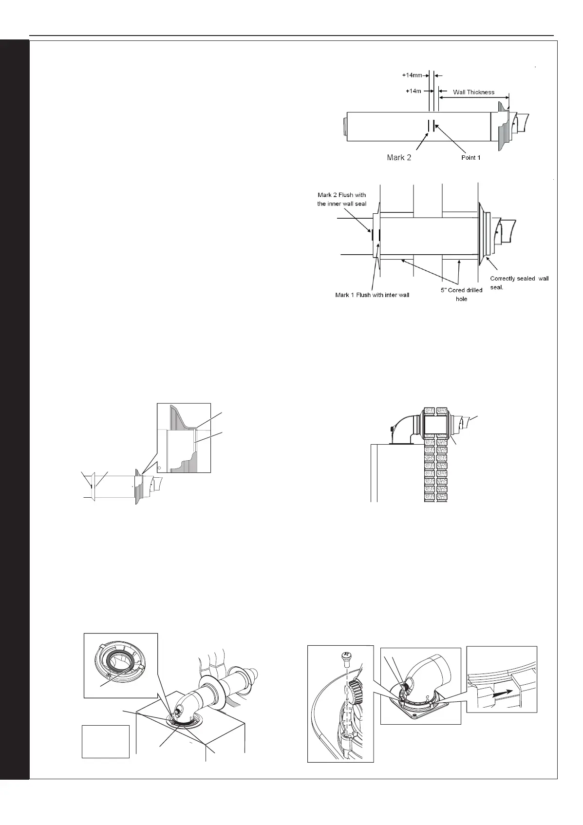
1. Measure wall thickness and add 14mm.
2. Measure from the outer terminal lip towards the end of outer ue, place a
small location mark at the dimension acquired at point 1.
3. Add a further 14mm to the dimension, obtained at item 1 (point 1) and
place an additional small location mark.
4. Fit external black wall seal ensuring the inside of the outer lip is in contact
with the terminal lip you have been measuring from (see g 1 below)
5. Fit the internal wall seal approximately 65mm before the outer of
the 2 location marks.
6. For an internal t place ue terminal in the centre of the 5” drilled
hole in the wall. Apply pressure and lightly move the ue left to
right or up and down. This will cause the outer ange to fold in
and allow the ue to pass through the wall.
7. Push through a further 65mm or until the inner ange is pressed
against the inner wall. This will allow the outer ange to return to
its original shape.
8. Pull back the ue until the rst of the 2 location marks is level with
the internal face of the wall.
Note. If the 2 location marks are not visible then the ue is not
pulled back far enough to obtain the correct seal. If the 1st location mark has passed the face of the wall the ue has been
pulled too far back and the outer wall seal will have been dislodged from its mounting and will need to be retted.
9. When 1st mark is in line with the wall, whilst holding the ue rmly, push the white wall sealing ange to the wall until the 2nd
of the two marks is just visible. If the last location mark is clearly past the white inner wall seal then the outer wall seal will
have been dislodged from its mounting and will need to be re-tted.
10. Ensure the seam and the outlet terminal are at the top and tted as shown.
Note. If less than 50% of the length of the ue is internal the ue should be tted from outside.
FITTING THE TURRET - Ensure the condense trap/siphon is lled with water
1. Ensure the rubber seal is tted correctly on the appliance manifold and that all ue seals are undamaged.
2. Hold the ue rmly and push the turret on until it has travelled 30mm on to the ue pipe and is fully engaged. Make sure the
ue has not rotated or moved forward during tting and the ue seam is uppermost.
3. Push the turret into the manifold ensuring the upper plastic lip is ush with the top of the manifold.
4. Fully engage the clamp location section into the manifold location holes. Rotate down on to turret ange.
5. Secure clamp to appliance using securing screw.
6. Ensure all sample points are accessible and all sample plugs and caps are tted.
Ensure lip of wall seal is positioned
over step on plastic nose of flue terminal
(note, seal is cut away for clarity)
Terminal Lip
Wall Seal Lip
Location
mark 1
2
Rubber
Terminal
Wall Seal
Terminal
MUST be
fitted as
shown
Retaining
screw
Clamp Lugs
Sample points
Flue Outlet
C
A
A - Duct Assembly
B - Flue Turret
C - Turret Clamp
D - Seal
Flue Outlet
D
B
Fig 1
 Loading...


