52
Installation and Servicing
SECTION 3 - SERVICING
1. Refer to Sections 3.8.
2. Drain down the boiler. Refer to Sections 3.21.
3. Unplug the electrical lead.
4. Unscrew the thermistor (to facilitate removal a
13mm socket spanner should be used).
5. Fit the new thermistor using the sealing
washer provided.
6. Reassemble in the reverse order.
7. Rell the boiler. Refer to Section 2.16.
8. Check that the boiler operates in both DHW &
CH modes.
3.30 FLOW THERMISTOR REPLACEMENT
4
3
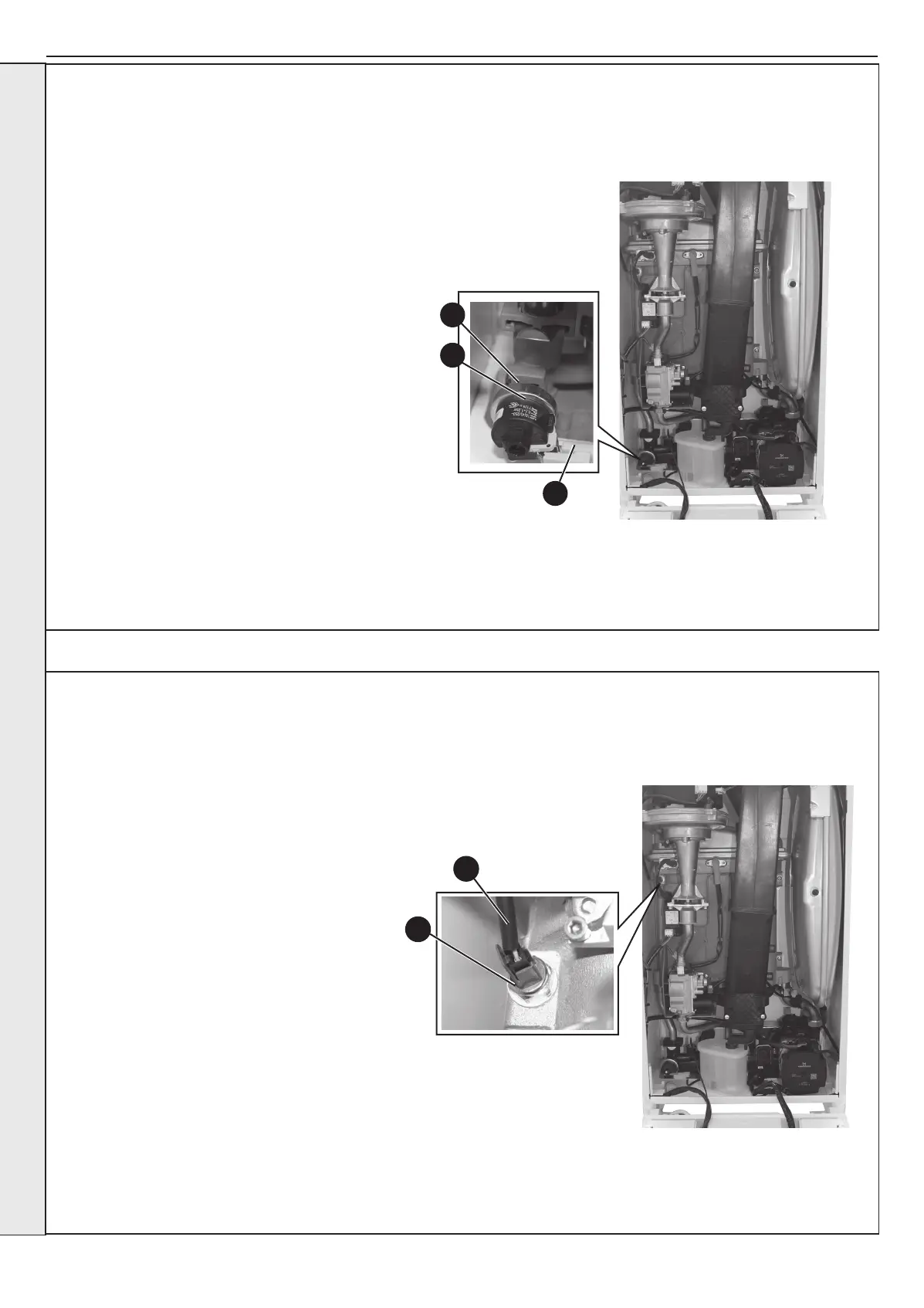
3.29 CH WATER PRESSURE SWITCH REPLACEMENT
1. Refer to Section 3.8.
2. Drain the boiler. Refer to Section 3.21.
3. Pull off the two electrical connections.
4. Using a suitable tool, pull out the metal retaining
clip.
5. Carefully withdraw the pressure switch.
6. Fit the new pressure switch and re-assemble in
reverse order.
7. Rell the boiler. Refer to Section 2.16.
8. Check that the boiler operates in both DHW & CH
modes.
3
4
5
SERVICING
 Loading...


