26
Installation and Servicing
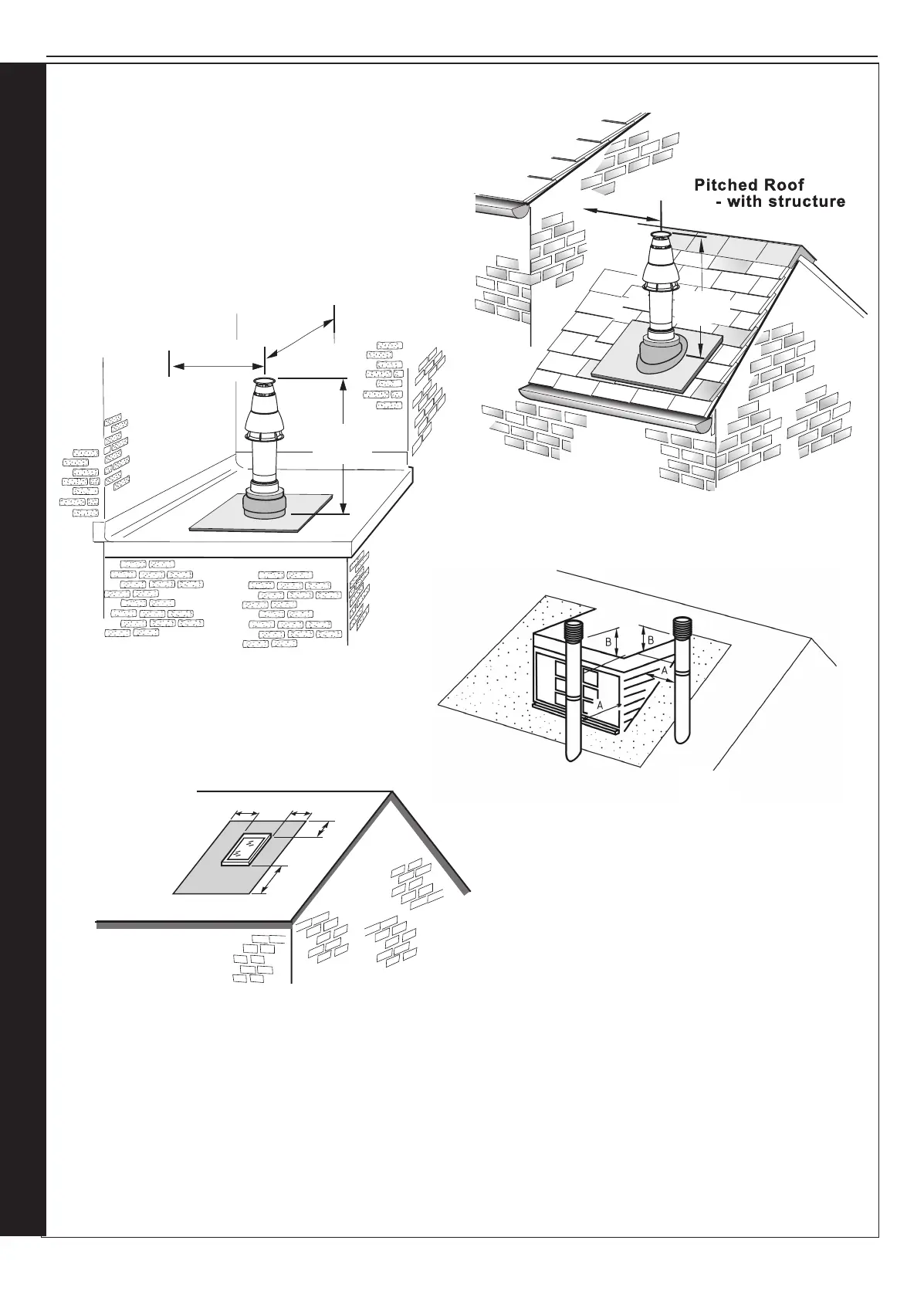
FLUE OUTLET
SECTION 2 - INSTALLATION
rf8394-1
690mm
Fixed
300mm
min
2.13 FLUE TERMINAL POSITION
rf8393-1
300mm
min
300mm
min
625mm
Fixed
Flat roof - with structure
The terminal should be positioned so that products of
combustion can safely disperse at all times.
Pluming may occur at the termination so, where possible,
terminal positions where this could cause a nuisance
should be avoided.
Minimum dimensions are shown below
RF9807
A
A
B
A
A = 600mm
B = 2000mm
The flue terminal shall not penetrate the shaded area of the roo
f
Note.
The equivalent ue length
resistance of the elbow kits are:
90
o
elbow kit = 1m
45
o
elbow kit = 0.6m
If chimney penetrates dotted area such that A is less
than 300mm, B shall not be less than 300mm.
Where two or more vertical fanned draught chimney congurations terminate in close
proximity at the same height, they shall be separated by at least 300mm. Where any one
vertical outlet is more than 300mm above the other, then they shall be separated by at least
1500mm.
Where any vertical fanned draught chimney conguration outlet is within 2000mm measured
horizontally of an opening window, then it shall be at least 300mm above the opening.
Pitched roof - with velux window
or opening
 Loading...


