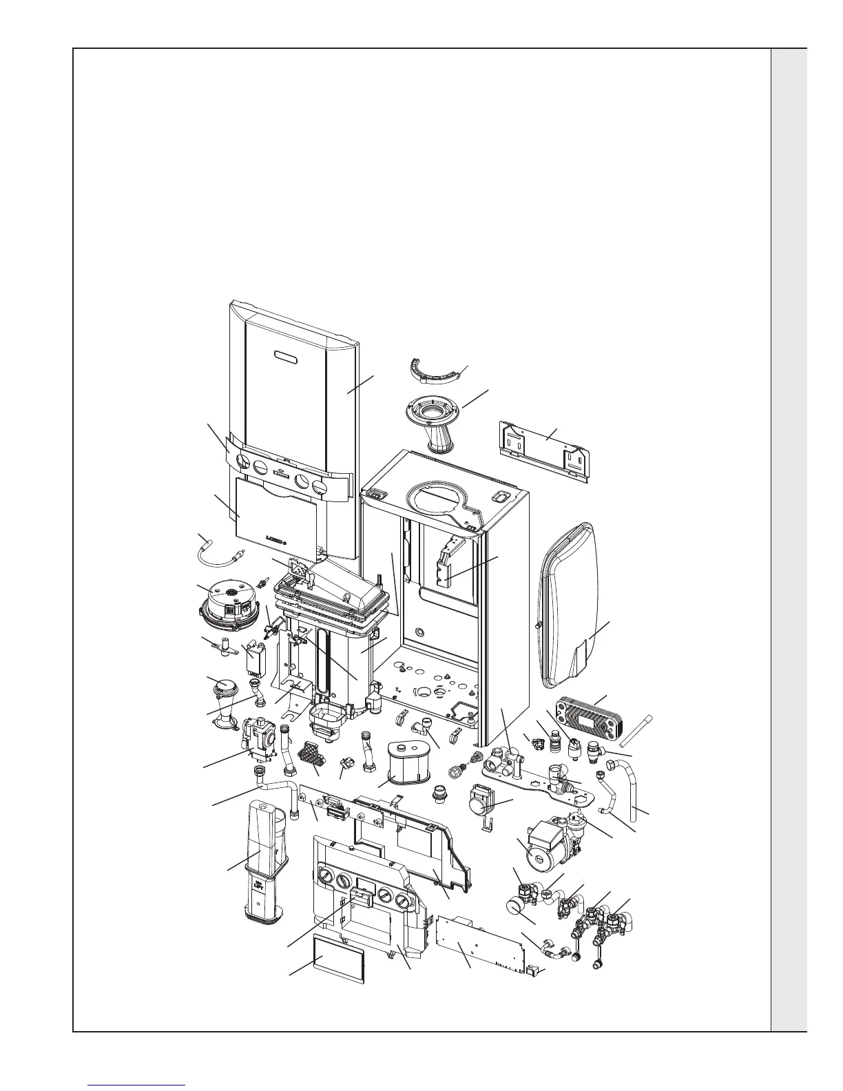
104 CH Return Valve
105 CH Flow Valve
106 DHW Inlet & Outlet
107 Filling Loop
108 Pump Head
110 Air Vent Pump
111 Divertor Valve Head
112 Divertor Valve Cartridge
113 Pressure Relief Valve
114 Pipe - PRV Outlet
115 Pipe - Flow
116 Pipe - Return
117 Pipe - Expansion Vessel
118 Expansion Vessel
119 Return Group Manifold
120 Flow Group Manifold
121 Plate Heat Exchanger
127 Flow Sensor Hall Effect
128 Flow Turbine Cartridge
131 Water Pressure Transducer
135 Pressure Gauge
203 Gas Cock
204 Pipe - Gas Inlet
205 Gas Valve
206 Pipe - Gas Injector
211 Injector Assembly
214 Venturi
215 Fan
217 Burner
218 Gasket - Burner
219 Sump Clean Out Cover
223 Flue Manifold
224 Flue Manifold Top
227 Clamp Retaining Flue Turret
228 Hose Condensate Internal
229 Siphon Trap
231 Condensate Outlet Connection
301 Ctrl Box Fixings Hings & Spring
302 Primary PCB*
303 CUI Board
304 Control Thermistor (Return)
306 Electrode Ignition
307 Electrode Detection
308 Ignitor Unit
309 Thermistor Flow
313 Ignition Lead
314 Control Box Lens
324 Control Box Lid
325 Control Box Front
326 Programmer Insert
401 Heat Engine
503 Wall Mounting Bracket
504 Front Panel
505 Fascia
506 Bracket - Gas Valve
507
Bracket - Expansion Vessel
136 Safety Valve Drain Pipe
512 Drop Down Door
* Note that production boiler PCBs are
factory pre-set to operate for boiler range
and output, but when ordering Primary
PCB as a spare, an additional Boiler Chip
Card (BCC) MUST also be purchased for
your specic boiler range and output.
Check boiler serial letter code on data
plate to obtain correct BCC.
INSTALLATION