EasyManuals Logo

IDEAL LOGIC + Combi 24 User Manual

IDEAL LOGIC + Combi 24
68 pages
To Next Page IconTo Next Page
To Previous Page IconTo Previous Page
Page #22 background imageLoading...
Page #22 background image
22
INSTALLATION
Ideal Logic + Combi - Installation and Servicing
FLUE OUTLET
rf8394-1
690mm
Fixed
300mm
min
20
FLUE TERMINAL POSITION
rf8393-1
300mm
min
300mm
min
625mm
Fixed
Flat roof - with structure
The terminal should be positioned so that products of
combustion can safely disperse at all times.
Pluming may occur at the termination so, where
possible, terminal positions where this could cause a
nuisance should be avoided.
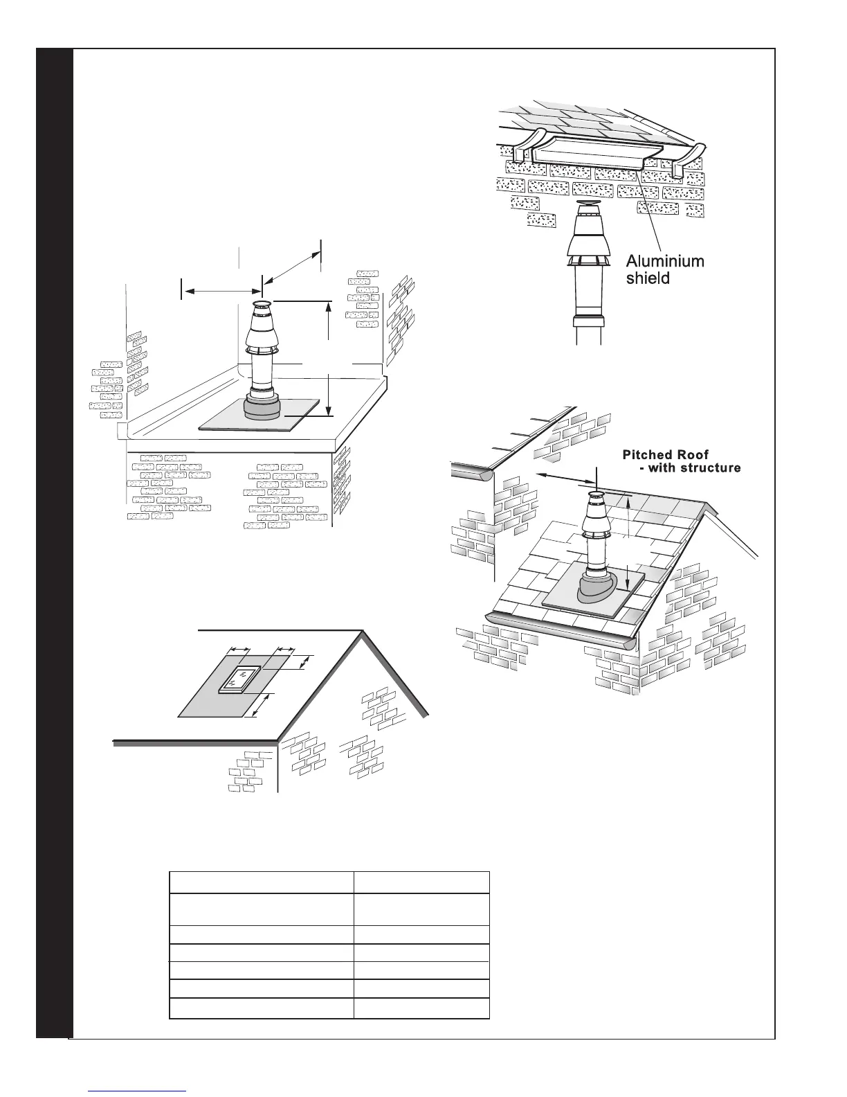
Minimum dimensions are shown below
Terminal Position Minimum Dimension
Directly below an opening,
air brick, windows, etc. 300 mm
Below plastic / painted gutters 300 mm
Painted surface 300 mm
Below eaves or balcony 500 mm
Below velux windows 2000mm
Above or side of velux windows 600mm
rf8392
Note.
The equivalent ue length resistance of the
elbow kits are:
90
o
elbow kit = 1m
45
o
elbow kit = 0.6m
RF9807
A
A
B
A
A = 600mm
B = 2000mm
The flue terminal shall not penetrate the shaded area of the roo
f

Questions and Answers:

Question and Answer IconNeed help?

Do you have a question about the IDEAL LOGIC + Combi 24 and is the answer not in the manual?

IDEAL LOGIC + Combi 24 Specifications

General IconGeneral
ModelLOGIC + Combi 24
CategoryBoiler
Boiler TypeCombi
Fuel TypeNatural Gas
Output24 kW
Efficiency94%
Dimensions700 x 395 x 278 mm
Warranty7 years
Max Working Pressure3 bar
Central Heating Flow Temperature Range30 - 80 °C

Related product manuals