53
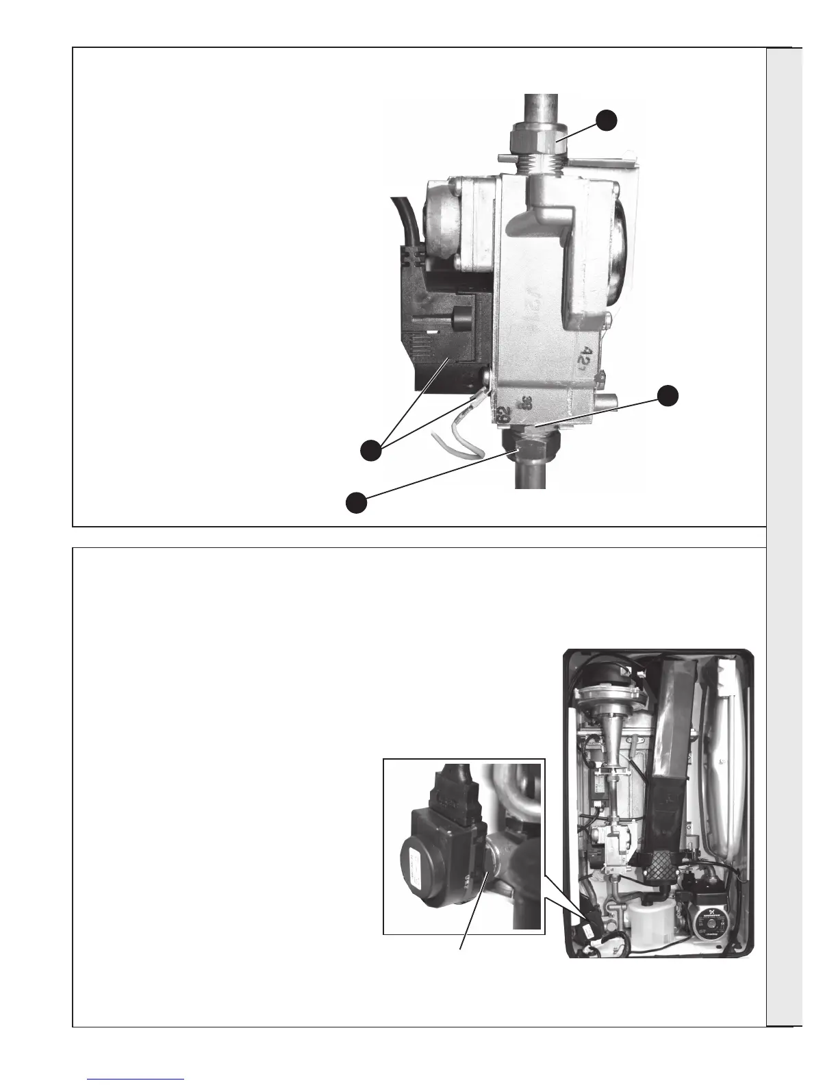
GAS CONTROL VALVE REPLACEMENT
1. Refer to Frame 45.
2. Unplug the electrical plug connection from the
gas control valve and disconnect the earth wire.
3. Undo the union nut on the outlet of the gas
control valve.
4. Undo the gas inlet pipe union at the inlet to the
gas control valve.
5. Loosen the back nut retaining the valve to the
bracket and withdraw the valve forwards.
6. Fit the new gas control valve ensuring the two
sealing washers are in place and reconnect gas
and electrical connections.
7. Check operation of the boiler. Refer to Frames
32-36.
54
DIVERTER VALVE ACTUATOR REPLACEMENT
1. Refer to Frame 45.
2. Remove the electrical plug.
3. Using a suitable tool pull out the retaining
clip and lift the diverter head from the brass
body.
4. Fit new actuator head and reassemble in
reverse order.
6. Check operation of the boiler. Refer to
Frames 32-36.
Diverter Valve Actuator
2
4
Retaining Clip
5
3
SERVICING