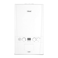
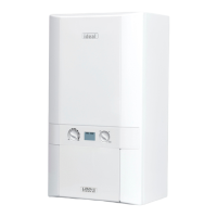
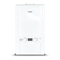
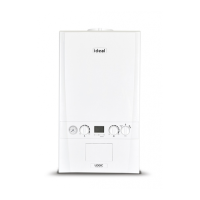
EasyManuals Logo

IDEAL Logic+ SYSTEM 15 User Manual

IDEAL Logic+ SYSTEM 15
72 pages
To Next Page IconTo Next Page
To Previous Page IconTo Previous Page
Page #17 background imageLoading...
Page #17 background image
17
INSTALLATION
Ideal Logic + System - Installation and Servicing
A
D
B
CE
8

1. Loosen the 2 screws retaining the front panel.
2. Pull the two spring clips downwards to disengage.
3. Pull the front panel forward and upwards to remove.
1
2
7


A Telescopic ue terminal
B Flue turret
C Rubber terminal wall seal
D Screw
E Sealing Tape
F Wall Seal (white)

A Flue terminal
B Flue turret
C Rubber terminal wall seal
D Cutting Aid
E Wall Seal (white)
Note. This ue system incorporates a removable ue outlet nose that utilises a push t location system. This enables the
installation of deector, high level or balcony outlet ue kits without the removal of the whole ‘B’ pack terminal. The appliance
must not be operated without the desired outlet nose correctly tted in place.
Note. Location dimples must be aligned with terminal mounting frame.
INSTALLATION
Questions and Answers:

Question and Answer IconNeed help?

Do you have a question about the IDEAL Logic+ SYSTEM 15 and is the answer not in the manual?

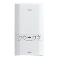
IDEAL Logic+ SYSTEM 15 Specifications

General IconGeneral
ModelLogic+ SYSTEM 15
CategoryBoiler
Output Rating15 kW
ErP RatingA
Fuel TypeNatural Gas
Dimensions (H x W x D)700 x 395 x 278 mm
TypeSystem Boiler
MountingWall Mounted
ERP Heating Efficiency93%
Standard Warranty7 Years

Related product manuals