51
SERVICING
60
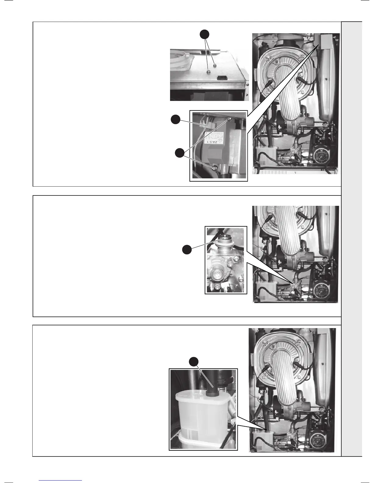
SPARK GENERATOR REPLACEMENT
61
GAS CONTROL VALVE REPLACEMENT
1. Refer to Frames 45 & 46.
2. Refer to Frame 53.
3. Remove the 2 securing screws at the top of the
casing, ensuring the expansion vessel is safely
supported, and withdraw the spark generator assy.
4. Disconnect the leads from the generator.
5. Remove 2 securing screws.
6. To replace connect all wiring and then x the
generator in position using the 2 securing screws,
ensuring the earth lead is rmly xed under the
lower securing screw, and the expansion vessel is
correctly located.
7. Secure the spark generator assy using 2 screws in
the top of the case.
8. Check the operation of the boiler. Refer to Frames
32-35.
1. Refer to Frames 45 & 46.
2. Refer to Frame 53.
3. Remove the gas inlet pipe. Refer to Frame 55.
4. Unplug the electrical connection.
5. Disconnect the earth lead at the rear of the gas valve.
6. Disconnect the gas service valve
7. Remove the 2 securing screws in the underside of the
boiler casing and remove the valve.
8. Remove brass injector from gas valve outlet and re-t
into replacement valve.
9. Replace in reverse order ensuring all seals are in good
condition and the assembly is gas sound.
10. Check the operation of the boiler. Refer to Frames 32-35.
5
4
3
62
CONDENSATE TRAP REPLACEMENT
1. Refer to Frames 45 & 46.
2. Refer to Frame 53.
3. Remove the rubber condensate pipe from
the top of the trap.
4. Rotate the trap clockwise to disengage
the trap and lift clear of the outlet
connection.
5. Ret in reverse order making sure the
trap is engaged with the outlet connection
6. Rell the condensate trap.
7. Check the operation of the boiler. Refer to
Frames 32-35.
3
8
SERVICING
 Loading...