Wireless
Note: Older wireless hardware devices will not work with the X-Series, Duevi integration. Please
make sure that you have the correct devices.
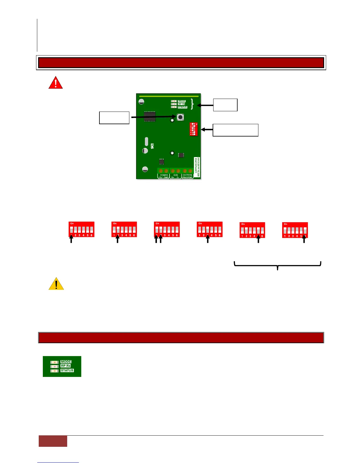
IDS & Duevi integration PCB:
1. DIP switch operation
The Dipswitch currently has only two operations. The first is to set the device address on the X-
Series bus. This is done in binary the same as was done for the wired expander save for one
difference. That is that these expanders each cater for 16 zones and not 8 like the wired expander.
Dip 1 Dip 2 Dip 1&2 Dip 3 Dip 5 Dip 6
Zones 1 – 16 Zones 17 – 32 Zones 33 – 48 Zones 49 – 64 PGM 1 PGM 2
RF JAM Supervision Loss
Programmable Output
Note: When dip switch 5 and 6 are:
OFF the outputs are then programmable.
ON the outputs are by default set to output 1 RF jam and output 2 supervision loss
2. Default
The second operation is a standalone default feature. If all Dip-switches are ON during power-up
then the unit will default. Please power down after, set appropriate address and power up to
resume normal operation.
LED operation
There are 3 LEDs on the board marked “MODE”, “RF RX” and “STATUS”.
STATUS: LED that will indicate whether the receiver is connected and communicating.
ON indicates good bus communication with the system.
RF RX: LED that will indicate when the receiver received a message from a learnt detector
MODE: Indicates current operating errors. Errors are indicated much the same as the wired expander.
If the LED is ON continuously then there are no errors. However if there are errors it will start pulsing
the error number. These error pulses will be separated by a 1sec pause with the LED off.
Pulse error number:
1. Duevi receiver module not responding
2. No activity on the X-Series serial bus
3. No X-Series messages detected