22
※ iTDC Quick Installation Guide
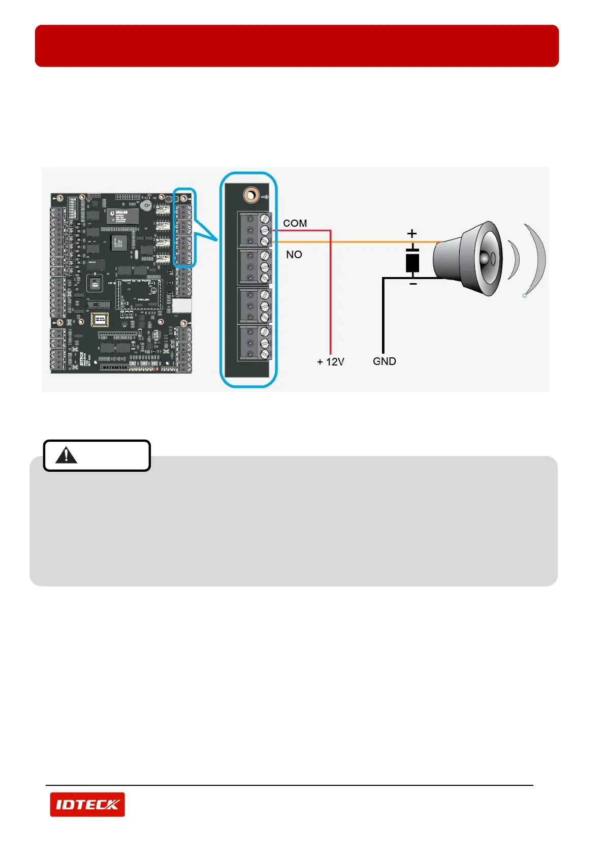
3.6.2 ALARM DEVICE WIRING
- Connect +12V wire of DC12V power supply to Output Port terminal block (RCOM2) of iTDC/iTDC-SR.
- Connect (+) wire of Alarm Device to Output Port terminal block (RNO2) of iTDC/iTDC-SR.
- Connect (-) wire of Alarm Device to GND(-) wire of the DC12V power supply.
- Must connect an anti-inverse voltage diode between (+) wire and (-) wire of Alarm Device. [IMPORTANT]
(Figure: Alarm Wiring)
Connect an anti-inverse voltage diode as shown above when wiring Door Lock or Alarm. If you
don’t an anti-inverse voltage diode, external noise flows in then it causes some malfunctions such
as poor communication, unintended changes in system setting etc. Also if you connect the
polarity of diode oppositely, the product can be damaged. So, must connect it in the correct
direction. 1N4004 – 1N4007 or equivalent diode are included in the gift box. When you install
automatic door, install an additional 24V relay between the product and a door lock.