4 - HANDLING AND INSTALLATION KID 70
GB
4 - Pag. 13 / 21
4.8 INSTALLATION PHASES
Below are listed the installation steps. For further details see the relating sections.
Loading axis height variation (section 4.8.1)
Magazine positioning (section 4.8.2)
Alignment and levelling (section 4.8.3)
Bar feeder fastening (section 4.8.4)
4.8.1 Loading axis height variation
The bar feeder is generally supplied with the
loading axis height aligned to that of lathe
spindle. If you need to change it, proceed as
follows:
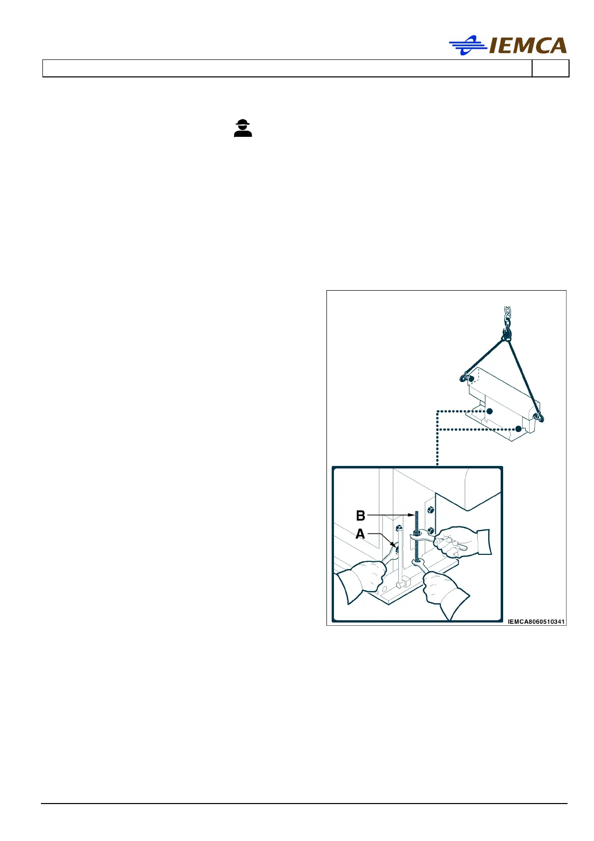
- Prepare the bar feeder to be lifted (sect. 4.4.).
- Stretch the ropes.
- Loosen, on both sides, the screws (B) and
remove the screws (A).
- Bring the bar feeder to the loading axis height
(see section 2.6. "Loading axis height" table).
- Refit the screws (A) and temporarily adjust
the screws. (B).