CabinetModule CR2012
16
8.2 Connecting, operating and display elements
CR2012 Technical data
Operating and indicating elements
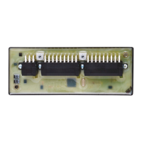
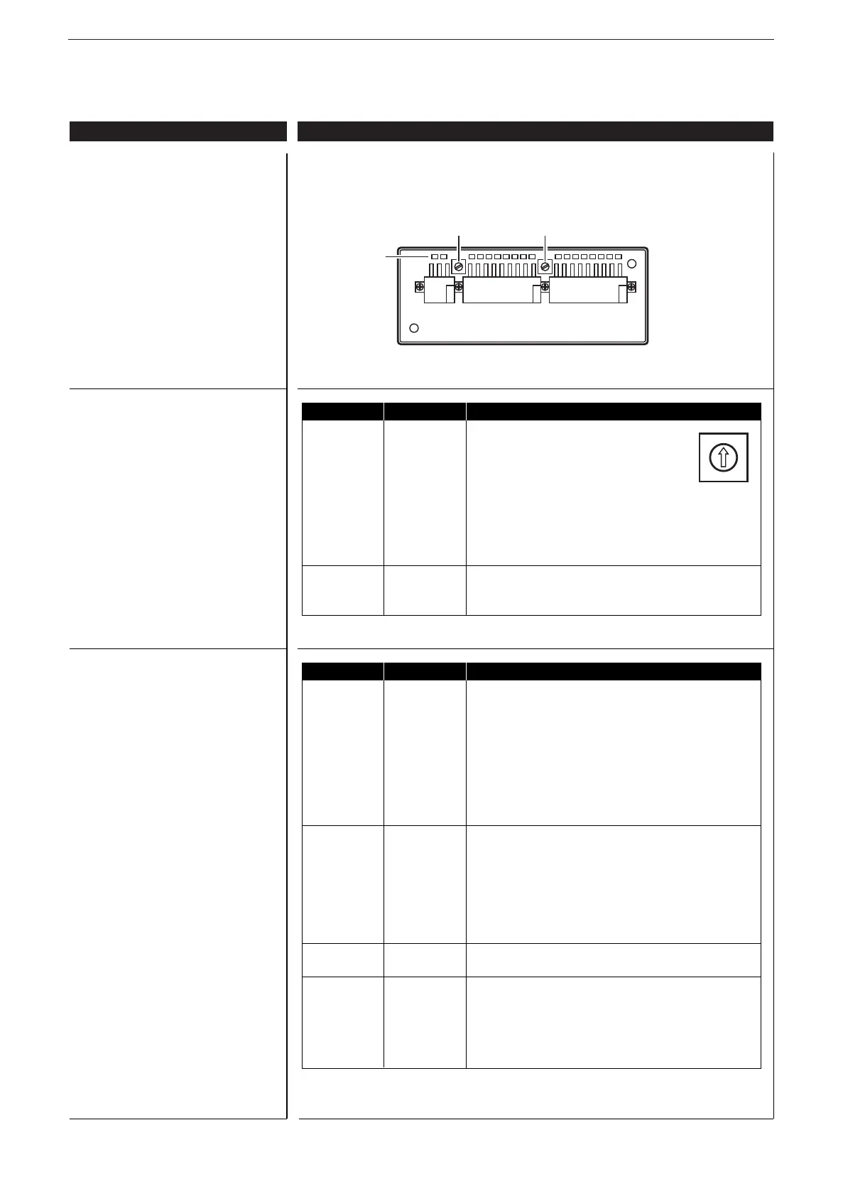
Connector
Hex-code switch coding
Operating states (LEDs)
ifm electronic gmbh • Friedrichstraße 1 • 45128 Essen
25.04.2013We reserve the right to make technical alterations without prior notice! CR2012 / page 2
LED State Description
PWR (green) OFF no supply voltage
ON module in stand-by mode
CANopen status: PREOPERATIONAL / PREPARED
outputs = OFF
1 x ON module in stop mode
CANopen status: STOP
outputs = OFF
2.5 Hz module active
CANopen status: OPERATIONAL
outputs are updated
DIA (red) OFF communication OK
ON communication disturbed, CAN bus OFF
1 x ON communication disturbed:
• CAN error warning level exceeded
2 x ON • node guard / heartbeat error
(if node guarding / heartbeat is activated)
3 x ON • no synch objects
(if synch monitoring is activated)
IN (yellow) OFF input not switched
ON input switched
OUT (yellow) OFF binary output not switched (OFF)
analogue output:
PWM preset value < 1% measuring range
ON binary output switched (ON)
analogue output:
PWM preset value > 2% measuring range
Switch Position Description
S1 0 1000 Kbits/s
Baud rate 1 800 kBits/s
2 500 Kbit/s
3 250 Kbit/s
4 125 Kbit/s
5 100 Kbit/s
6 50 Kbit/s
7 20 Kbit/s
8...E not defined
F adjustment via object directory (default)
S2 0 not defined
Node-ID 1...E 1...14
F adjustment via object directory (default)
0
•
2
•
4
•
6
•
8
•
A
•
C
•
E
•
Rotary switch
hex-coded
AMP
Crimp connector
S1
Baud rate
S2
Node ID