UK
CabinetModule CR2012
5
● There are 1 server SDO and 4 default PDOs according to CiA DS 401�The
PDO mapping can be changed (dynamic PDO mapping)�
The default identifiers are assigned according to the “predefined connection
set”�
● The COB IDs of the PDOs as well as the transmission type (synch/asynch) of
the individual PDOs can be configured�
● The device expects a synch object� The CAN identifier of the synch object can
be configured�
● The device supports “node guarding” and “heartbeat”� The “guard time”, the
“life time factor” and the “heartbeat time” can be configured�
● The device generates an emergency object� The COB ID of the EMCY object
can be configured�
● The device stores the last error� The error code of the corresponding emer-
gency object is stored�
● The device supports a reset function, i�e� the assignment of the parameters to
the factory default settings on request�
Factory default settings (→ 7.3 Communication profiles; Idx 1000 to 1FFF) and
(→ 7.4 Manufacturer-specific profiles; Idx 2000 to 6FFF)
4 Mounting
4.1 Mounting location
► The device is to be mounted in a dry and enclosed environment (e�g� control
panel of the driver‘s cab, separate control boxes, etc�)�
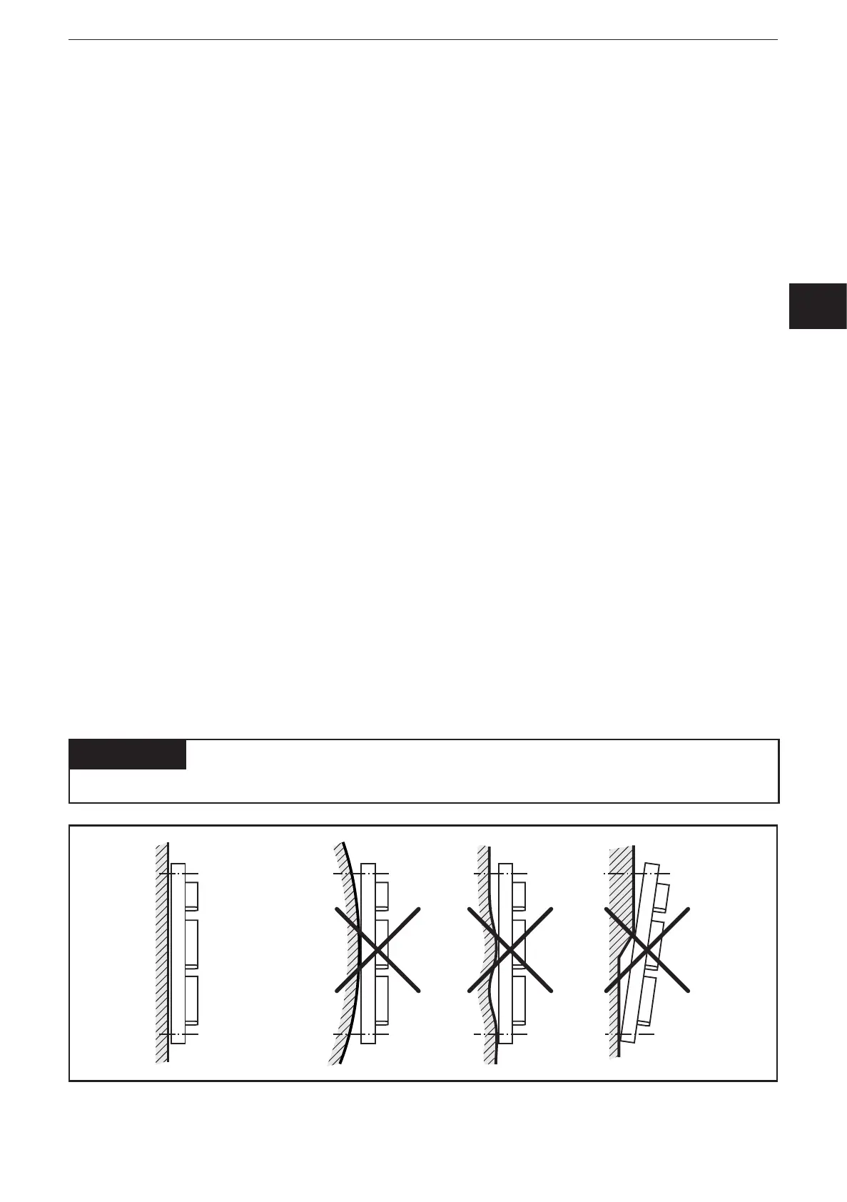
ATTENTION
The housing must not be exposed to any torsion forces or mechanical stress�