UK
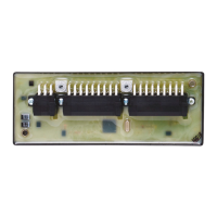
CabinetModule CR2012
17
8.3 Characteristics of the inputs/outputs, test standards and regulations
ifm electronic gmbh • Friedrichstraße 1 • 45128 Essen
25.04.2013We reserve the right to make technical alterations without prior notice! CR2012 / page 3
CR2012 Characteristics of the inputs / outputs
Inputs
Channels 1...4, channels 9...12 • 8 inputs for positive sensor signals
For each input the pins +U
B
and Bin INx are available
Channels 7...8, channels 15...16 • 4 inputs for positive sensor signals
Can be used as an alternative to the 4 outputs.
For input and output one pin is available (double configuration).
The inputs can be used to read back the output signals.
Current consumption I
IN
= 4 mA (for U
B
= 10 V)
I
IN
= 17 mA (for U
B
= 30 V)
Switching threshholds HIGH = 8 V LOW = 2.5 V
Switching frequency 25 Hz max. (for ti = tp)
Channels 5...6, channels 13...14 • 4 inputs, to be configured via CANopen:
for ratiometric measurement for potentiometric transducers (e.g. joystick)
For each input the pins +U
B
, Ana INx and GND are available
Input resistance typ. 50 kΩ
Resolution based on 1/2 supply voltage U
B
= ± 200 steps (for U
B
= 12 V), ± 400 steps (for U
B
= 24 V)
for absolute value measurement 0...10 V
For each input the pins Ana INx and GND are available
Input resistance typ. 50 kΩ
Resolution 8 bits
Accuracy typ. ± 2 LSB
as binary inputs
For each input the pins +U
B
and Bin INx are available
Input resistance typ. 50 kΩ
Switching threshhold at 1/2 supply voltage U
B
Outputs
Channels 7, 15 • 2 positive-switching outputs; short-circuit and overload protected;
the supply voltage U
B
is switched without additional fuse.
The output states can be read back (see inputs).
For each input the pins Bin OUTx and GND are available.
When inductive loads are switched, free-wheeling diodes must be connected in
parallel with the load!
Switching current max. 500 mA
Channels 8, 16 • 2 PWM outputs (high side), variable frequency
PWM frequency 20...250 Hz
Pulse duty factor 0...1000 ‰
Resolution 1 ‰
Switching current max. 500 mA
Test standards and regulations
Immunity to to ISO 7637-2, pulses 2a, 3a, 3b, 4, severity level 4, function state A
conducted interference to ISO 7637-2, pulse 5, severity level 3, function state A
to ISO 7637-2, pulse 1, 2b, severity level 4, function state C
Immunity to interfering fields to UN/ECE-R10 at 100V/m (E1 type approval)
and EN 61000-6-2: 2005 (CE)
Interference emission to UN/ECE-R10 (E1 type approval)
and EN 61000-6-3: 2007 (CE)
\DATEN\100\DB-FORM—PZD/03/12/96
Tests for railway applications EN 50155 clause 12.2 mechanical/climatic tests
EN 50121-3-2 EMC noise emission and noise immunity
additional information on request