4
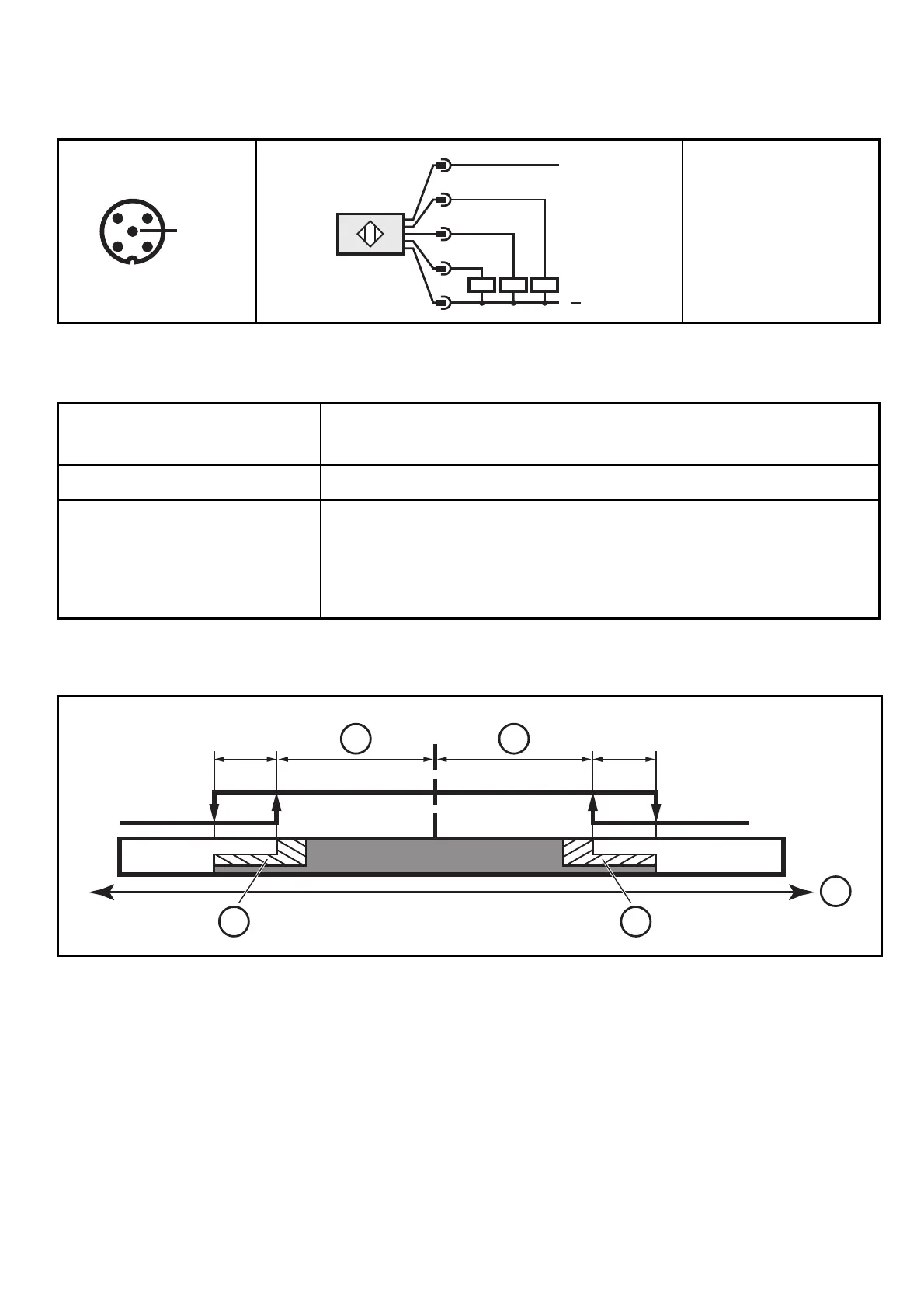
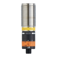
5 Electrical connection
► Disconnect the installation from power and connect the unit.
1
2
3
4
5
L
+
L
1
5
2
4
3
2: OUT 2
4: OUT 1 / IO-Link
5: OUT 3
5.1 Switching functions
OUT1 (pin 4) Communication IO-Link
Switching output valve position open in SIO mode
OUT 2 (pin 2) Switching output valve position closed
OUT 3 (pin 5) Programmable:
- Switching output valve position open
- Switching output valve position closed
- Fault output
6 Function diagram
OFF
HYS HYS
SP
OFFON
1: Tolerance range
2: Leak warning range
3: Angle of the valve
SP = set point
HYS = hysteresis