5
UK
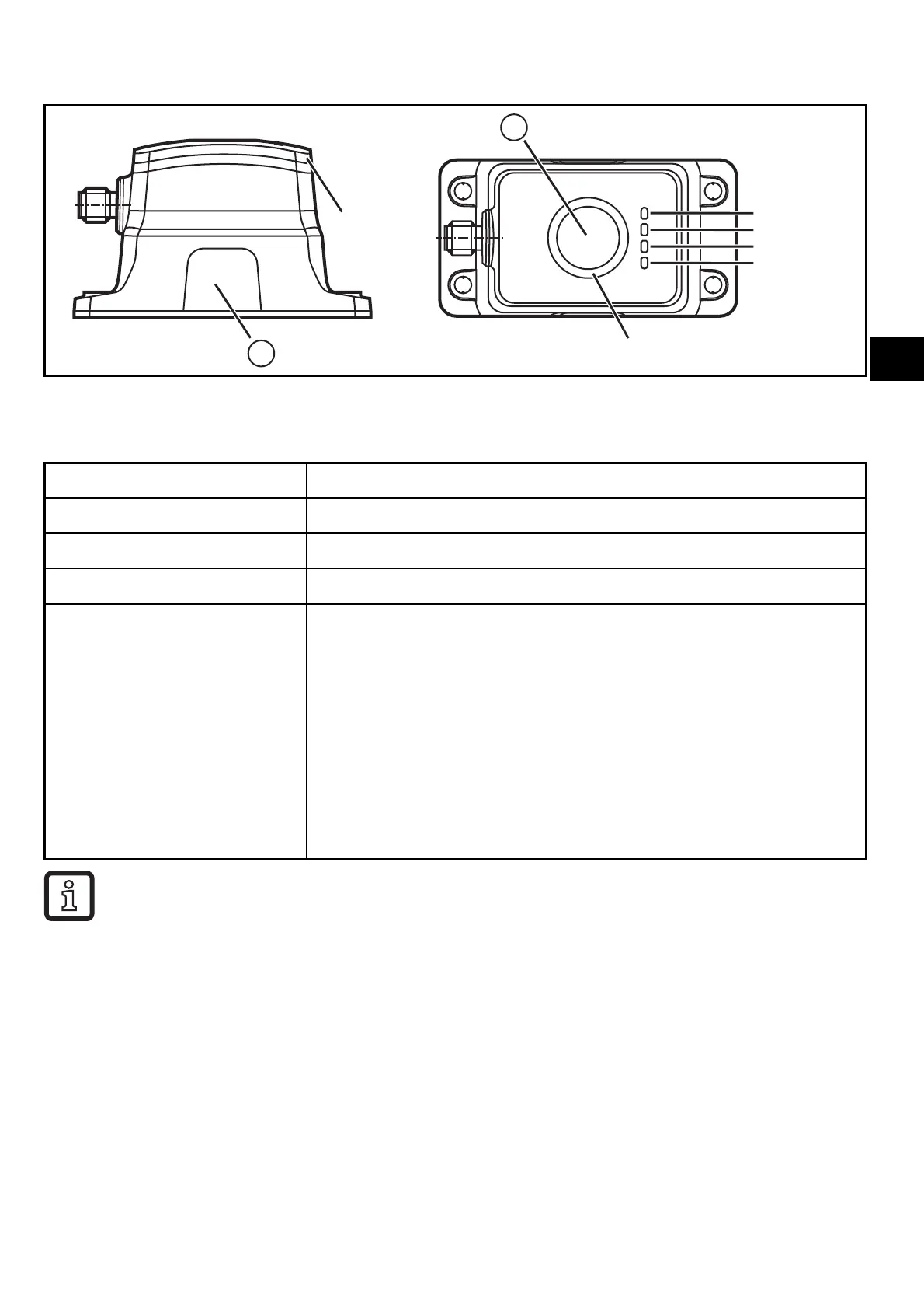
7 Operating and display elements
2
1
LED 5
LED 1
LED PWR
LED 4
LED 3
LED 5
1: Window for optical position indication (OPEN)
2: Inductive teach button
LED 1 yellow on switching status OUT1 – valve position open
LED 2 PWR green on voltage applied to the unit
LED 3 not used
LED 4 white on switching status OUT2 - valve position closed
LED 5 (ring) yellow on - switching status OUT1
blue on - switching status OUT2
(colours programmable, yellow and blue preset at the
factory)
red flashing - fault in the unit
• no pulse pick-up available
• teach error - switch points SSC1 and SSC2 overlap
• end position not reached after set time has elapsed
• unit faulty
The LED colours in the table are the default colours and can be customised.
8 IO-Link
This unit has an IO-Link communication interface which enables direct access to
process and diagnostic data. In addition it is possible to set the parameters of the
unit while it is in operation. Operation of the unit via an IO-Link interface requires
an IO-Link master.
With a PC, suitable IO-Link software and an IO-Link adapter cable communication
is possible when the system is not in operation.
 Loading...