Owner’s Manual &
Installation Instructions
Revision 6e
Page 22
Engine Cooling System cont’d
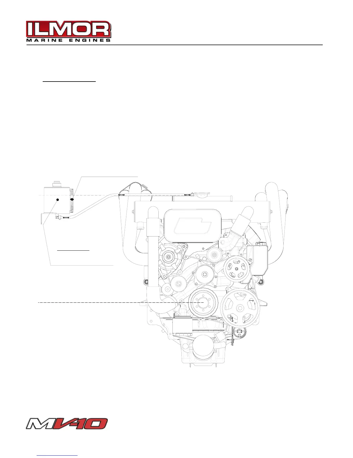
Expansion Tank
To ensure the engine remains completely filled with coolant the engine installer must fit an
expansion tank to the system. The tank must have at least a two quart capacity, be
vented to atmosphere and have a provision for checking the fluid level. A hose must be
routed from the pipe barb found on the heat exchanger filler neck to the bottom of the
expansion tank. This tank is ideally mounted in the bilge area in a location just below the
pressure cap found on the heat exchanger. If space is limited it can be mounted within the
area outlined in the diagram below.
COOLING SYSTEM DIAGRAM
EXPANSION TANK
Center of tank must be located
between filler neck and crankshaft
centerline.
FILL TILL WATER LEVEL IS IN
THE MIDDLE OF SIGHT TUBE
Fig. 15