Owner’s Manual &
Installation Instructions
Revision 6e
Page 32
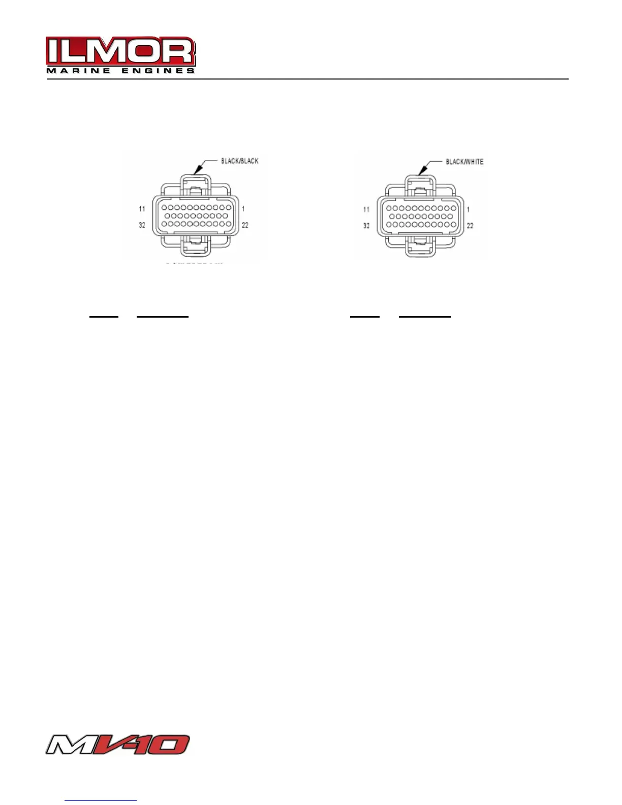
Electrical System - ECM Pin-Out
The powertrain control module utilizes three, color-coded, 32-pin connectors.
Connector A:
Connector B:
Pin #
Function Pin # Function
1 Ign. Coil Driver #4 1 -
2 Ignition Switch Output 2 Fuel Injector #7
3 Ign. Coil Driver #3 3 Fuel Injector #9
4 Sensor Ground 4 Fuel Injector #1
5 Ign. Coil Driver #5 5 Fuel Injector #3
6 - 6 Fuel Injector # 5
7 Ign. Coil Driver #1 7 -
8 Crankshaft Position 8 -
9 Ign. Coil Driver #2 9 -
10 Idle Air Control #1 10 Alternator Field Driver
11 Idle Air Control #2 11 -
12-15 - 12 Fuel Injector #6
16 Coolant Temperature Sensor 13 Fuel Injector #8
17 Supply Voltage (5V) 14 Fuel Injector #10
18 Camshaft Position Sensor 15 Fuel Injector #2
19 Idle Air Control #4 Driver 16 Fuel Injector #4
20 Idle Air Control #1 Driver 17-32 -
21 -
22 Fused B (+)
23 Throttle Position Sensor
24-26 -
27 MAP Sensor
28-30 -
31 Ground
32 Ground