Do you have a question about the ILMOR MV-10 and is the answer not in the manual?
Lists approved ILMOR MV10 parts available in the appendix of the manual.
Describes the front lift point using a dedicated bracket for attaching a lifting strap.
Explains the rear lifting point located in the accessory mounting plate.
Details standard front and rear plates for common v-hull and catamaran setups.
Describes center plates for single/triple engine boats and reinforced rear plates.
Details staggered plates used in twin engine v-hulls with limited space.
Explains side-by-side front mounting plates for specific engine configurations.
Describes the two required foot mounts for common boat/engine combinations.
Details Bravo style and Transmission style bell housings for drive system compatibility.
Describes the standard down-turned headers and optional tailpipes for Bravo applications.
Covers straight back headers used for special application needs.
Details "straight up" and "tipped-in" configurations for improved boat clearance.
Details USCG regulations for fuel system plumbing and component selection.
Visual representation of the fuel system components and their connections.
Explains the function and installation of the fuel filter/water separator.
Describes the fuel pump's "Smart Start" strategy and operation.
Details the fuel pressure regulator's role in managing fuel pressure.
Explains the dual-purpose cooling of fuel and engine oil by the fuel cooler.
Details adapter connections for the fuel filter/water separator.
Specifies electrical connections for the fuel pump.
Outlines connections for the fuel pressure regulator.
Illustrates the starboard and port side connections of the fuel/oil cooler.
Details the need for a sea strainer, pressure relief valve, and hose size.
Recommends specific power steering fluid and details the cooler connections.
Explains the correct order for connecting and disconnecting battery cables to prevent damage.
Provides instructions on how to safely remove the fuse box and ECU cover.
Illustrates the layout of fuses, relays, and the circuit breaker.
Details the function of each pin in the 9-pin engine/boat interface connector.
Lists wire colors and their corresponding functions for interface connections.
Lists pin functions for ECM connector A (BLACK/BLACK).
Lists pin functions for ECM connector B (BLACK/WHITE).
Explains the function of water temperature, oil temperature, oil pressure, and tachometer senders.
Covers optional instrumentation like hour meters and fuel/water pressure taps.
Provides detailed instructions for checking the engine oil level accurately.
Outlines the oil change interval and specifies oil capacity and type.
Illustrates the location of engine oil drain hoses for oil removal.
Specifies approved coolant type and the total system capacity.
Lists minimum/maximum resistance values for spark plug cables and ignition coils.
Provides torque values for camshaft and crankshaft position sensor screws.
| Fuel Type | Gasoline |
|---|---|
| Fuel System | Electronic Fuel Injection |
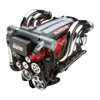
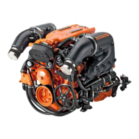
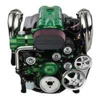
| Engine Type | V10 |
| Configuration | V10 |
| Valvetrain | DOHC 4 Valves per Cylinder |
| Cooling System | Liquid-cooled |
| Dry Weight | 476 lbs |