5-1
CHAPTER 5. GYRO connection
5.1 Connecting GYRO
Connect OIU and GYRO I/F Box with following the JUE-500 connecting diagram.
Below cable connections are required when connecting GYRO I/F Box. Depending on the
GYRO type (NMEA or SYNC/STEP), connection details are different.
5.1.1 NMEA GYRO connection
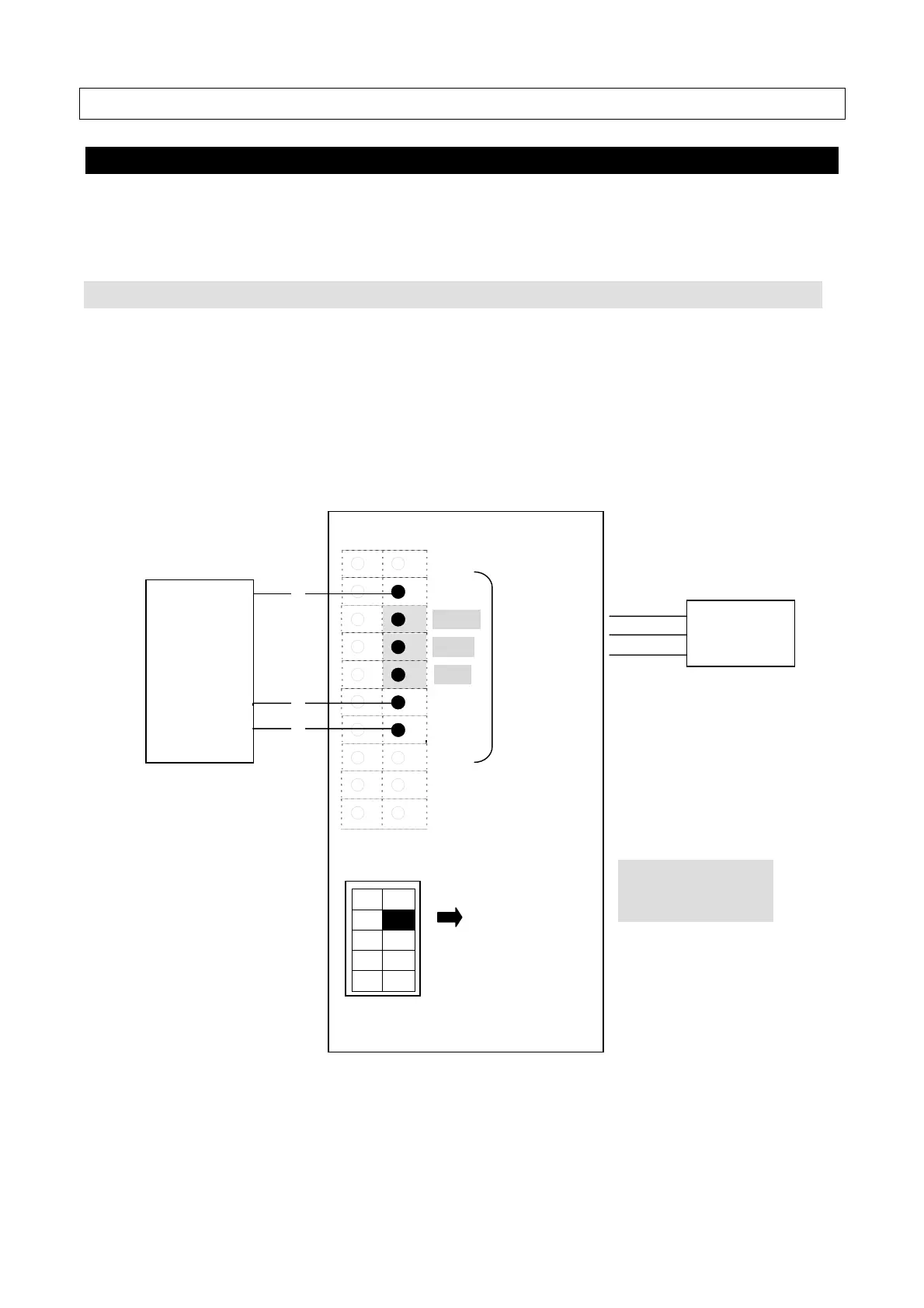
(1) Connect the output signal of NMEA GYRO to the [GYRO I/F] part of the terminal block of
OIU.
*Output of NMEA GYRO supports 4,800bps or 38,400bps.
(2) Set the [No.2] of [SW2] to [ON(NMEA)].
○ ○
○ ●
GND
○ ●
*)
+24V
○ ●
*)
TX+
○ ●
*)
TX- GYRO I/F
○ ●
RX+
○ ●
RX-
○ ○
○ ○
○ ○
SW2
(3) Set the TB2 of the GYRO I/F Box with following the figure in [5.1.3. GYRO I/F
setting](p5-4).
NMEA
GYRO
BDE
OIU
No.2
ON (NMEA)
*)
+24V, TX+, and TX-
are not in use