5-2
GYRO I/F Unit
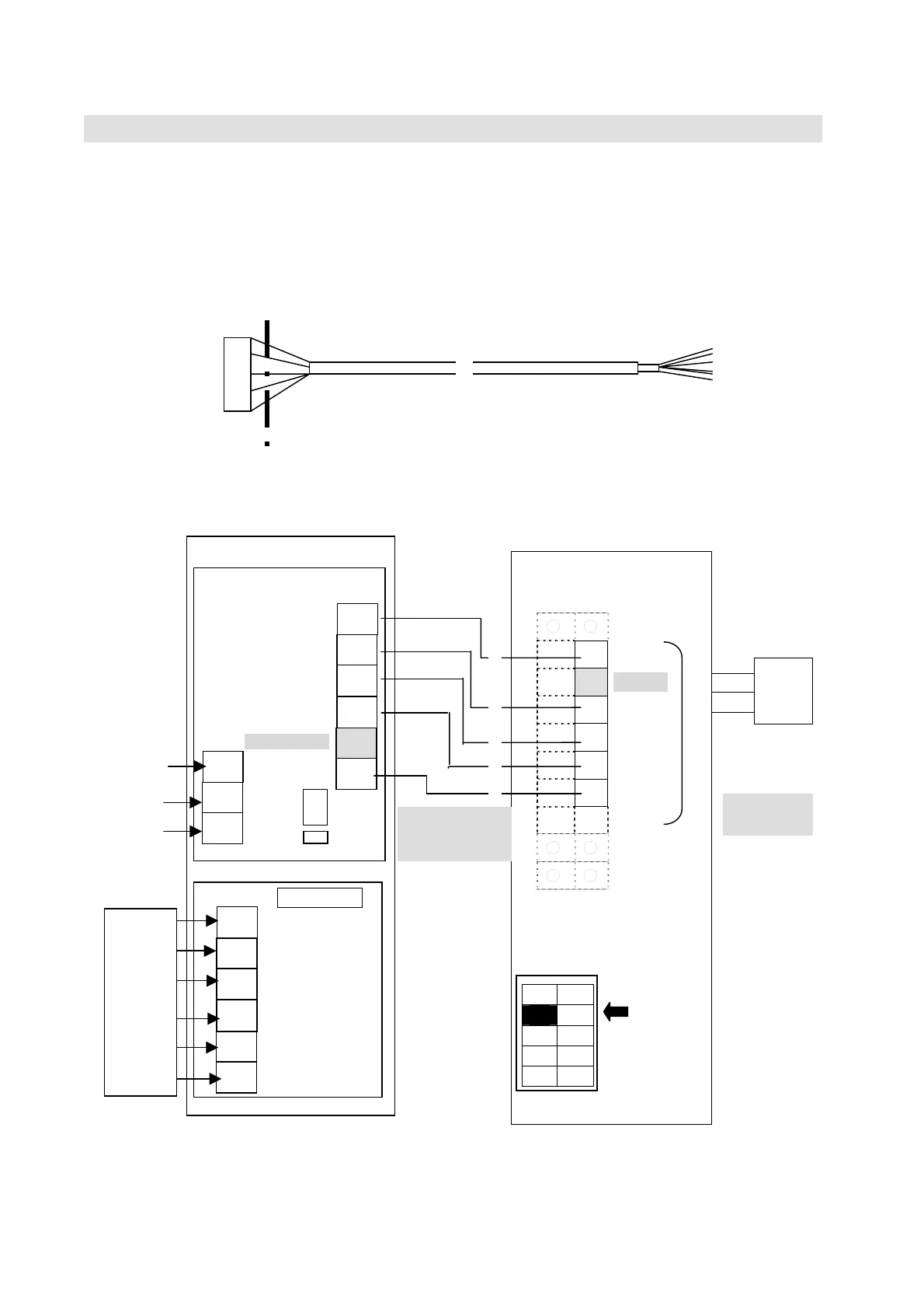
5.1.2 SYNC/STEP GYRO connection
(1) Connect GYROI/F Unit [NQA-2066] to GYRO I/F connecting area of OIU terminal block.
Cut the connector part of the cable H-7ZCSC0244, which is attached to GYRO I/F Box
(NQA-2066) and use it.
(2) Set the [No.2] of [SW2] on OIU board to [OFF(SYNC/STEP)].
The cable can be cut depending on the setting positions of OIU and GYRO I/F Box.
○ ○
○ ●
GND
○ ●
**)
+24V
○ ●
TX+
○ ●
TX-
○ ●
RX+
○ ●
RX-
○ ○
○ ○
○ ○
SW2
(3) Set the S201, TP1 and TP2 of GYRO I/F Box with following the figure in [5.1.3. GYRO I/F
setting](p5-4).
H-7ZCSC0244
Cut here
BDE
OIU
●
●
●
●
●
●
●
●
●
TB3
RD1
RD2
SD1
SD2
*)
NMEA-/NSK
GND
+24V
GND
(FG)
No.2
OFF
(SYNC/STEP)
**)
+24V is
not in use.
*)
NMEA-
NS
is not in use.
TB1
●
●
●
●
●
●
S201
SYNC/
STEP
GYRO
TB11
TP1
TP2
H-7ZCSC0244