3-2
10
6
1
3
2
7
6
5
4
5
6
5
5
6
10
9
9
8
8
8
10
10
8
9
11
11
9
19 - IE
INSTALLATORUSERTECHNICIAN
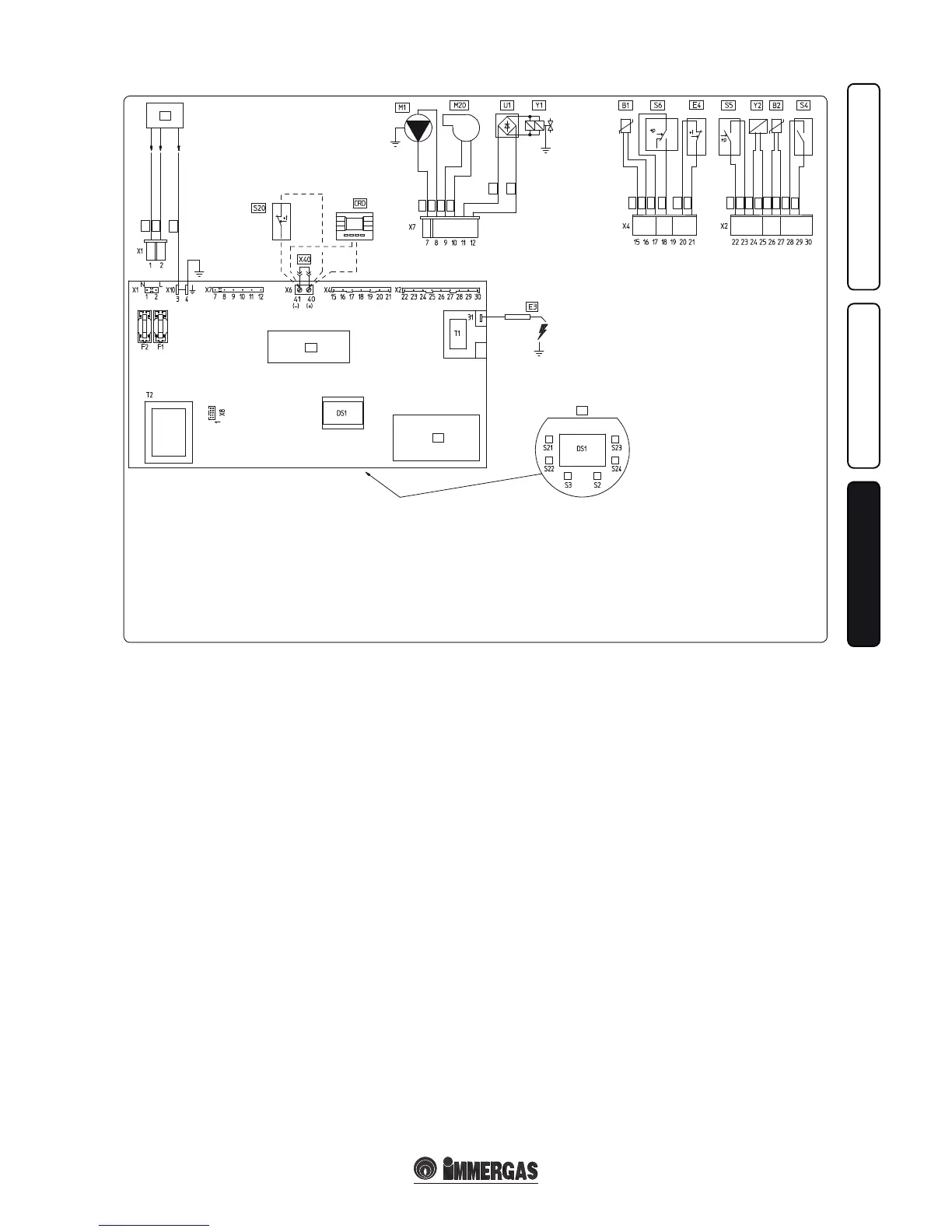
Key:
B1 - Delivery probe
B2 - Domestic hot water probe
DRC - Digital Remote Control (optional)
DS1 - Display
E3 - Ignition and detection electrodes
E4 - Safety thermostat
F1 - Phase fuse
F2 - Neutral fuse
3.2 WIRING DIAGRAM.
e boiler is designed for application of a room
thermostat (S20), an On/O room chronother-
mostat, a program timer or a Digital Remote
Control (DRC). Connect it to clamps 40 –41
eliminating jumper X40.
3.3 TROUBLESHOOTING.
N.B.: maintenance interventions must be carried
out by a qualified technician (e.g. Immergas
Aer-Sales Technical Assistance Service).
- Smell of gas. Caused by leakage from gas circuit
pipelines. Check sealing eciency of gas intake
circuit.
- e fan works but ignition discharge does not
occur on the burner ramp. e fan may start
but the safety air pressure switch does not
switch the contact over. Make sure:
1) the intake-exhaust duct is not too long (over
allowed length).
2) the intake-exhaust pipe is not partially blo-
cked (on the exhaust or intake side).
3) the diaphragm of the fume exhaust is adequa-
te for the length of the intake-exhaust duct.
4) that the sealed chamber is kept in good condi-
tions.
5) the fan power supply voltage is not less than 196
V.
- Irregular combustion (red or yellow ame).
is may be caused by: dirty burner, incorrect
combustion parameters, intake - exhaust ter-
minal not correctly installed. Clean the above
components and ensure correct installation of
the terminal.
- Frequent activation of the temperature over-
load thermostat. is may be caused by lack
of water in the boiler, insucient water circu-
lation in the circuit, a blocked circulator or an
anomaly of the boiler adjustment board. Check
on the manometer that the system pressure is
within established limits. Check that radiator
valves are not all closed.
- Presence of air in the system. Check opening of
the special air bleeding cap (Fig. 1-33). Make
sure the system pressure and expansion vessel
pre-charge values are within the set limits; the
pre-charge value for the expansion vessel must
be 1.0 bar, and system pressure between 1 and
1.2 bar.
- Ignition block paragraph 2.4 and 1.5 (electric
connections).
- Low water ow: if, as a result of lime scale (cal-
cium and magnesium), the domestic hot water
system does not work properly contact a qua-
lied technician for descaling e.g. Immergas
Aer-Sales Technical Service. Descaling must
be carried out on the domestic hot water side
of the bithermal heat exchanger in accordance
with good practice. To preserve integrity and
eciency of the heat exchanger, a non corro-
sive descaler must be used. Cleaning must be
carried out without the use of tools which can
damage the heat exchanger.
3.4 CONVERTING THE BOILER TO
OTHER TYPES OF GAS.
If the boiler has to be converted to a dierent gas
type to that specied on the data plate, request
the relative conversion kit for quick and easy
conversion.
Boiler conversion must be carried out by a
qualied technician (e.g. Immergas Aer-Sales
Technical Assistance Service).
To convert to another type of gas the following
operations are required:
- remove the voltage from the appliance;
- replace the main burner injectors, making sure
to insert the special seal rings supplied in the
kit, between the gas manifold and the injectors.
- apply voltage to the appliance;
- select, using the boiler key, the gas parameter
type (P1) and select (nG) in the case of methane
supply or (LG) in the case of LPG supply;
- adjust the boiler nominal heat output;
- adjust the boiler nominal heat output in dome-
stic hot water phase;
- adjust the boiler nominal heat output in heating
phase;
- adjust (eventually) the maximum heating
power;
- seal the gas ow rate devices (if adjusted);
- aer completing conversion, apply the sticker,
present in the conversion kit, near the data-
plate. Using an indelible marker pen, cancel
the data relative to the old type of gas.
ese adjustments must be made with reference
to the type of gas used, following that given in
the table (Parag. 3.17).
M1 - Boiler circulating pump
M20 - Fan
S2 - Selector switch functioning
S3 - Reset block keys
S4 - Domestic hot water ow switch
S5 - System pressure switch;
S6 - Fumes pressure switch
S20 - Room thermostat (optional)
S21 - Domestic hot water temperature
increase key
S22 - Domestic hot water temperature
decrease key
S23 - Heating temperature increase key
S24 - Heating temperature decrease key
T1 - Switch-on transformer
T2 - Boiler board transformer
U1 - Rectier inside the gas valve
connector (Only available on
Honeywell gas valves)
X40 - Room thermostat jumper
Y1 - Gas valve
Y2 - Gas valve modulator
1 - User interface
2 - N.B.: e user interface is on the
welding side of the boiler board
3 - e X6 connector is used for
automatic inspection
4 - 230 Vac 50Hz power supply
5 - Blue
6 - Brown
7 - Yellow/Green
8 - Black
9 - Grey
10 - White
11 - Red