1-32
A
C
B
D
13 - IE
INSTALLATORUSERTECHNICIAN
1.11 FUME EXHAUST TO FLUE/
CHIMNEY.
Flue exhaust does not necessarily have to be con-
nected to a branched type traditional ue. Flue
exhaust can be connected to a special LAS type
multiple ue. Multiple and combined ues must
be specially designed according to the calculation
method and requirements of the standards, by
professionally qualified technical personnel.
Chimney or ue sections for connection of the
exhaust pipe must comply with requisites of
technical standards in force.
1.12 DUCTING OF EXISTING FLUES.
With a specic “ducting system” it is possible
to reuse existing ues, chimneys and technical
openings to discharge the boiler fumes. Ducting
requires the use of ducts declared to be suitable
for the purpose by the manufacturer. Follow the
installation and user instructions provided by the
manufacturer and the requirements of standards.
1.13 FLUES, CHIMNEYS AND CHIMNEY
CAPS.
e ues, chimneys and chimney caps for the
evacuation of combustion products must be in
compliance with applicable standards.
Positioning the dra terminals. Dra termi-
nals must:
- be installed on external perimeter walls of the
building;
- be positioned according to the minimum di-
stances specied in current technical standards.
Fume exhaust of forced draught appliances in
closed open-top environments. In spaces clo-
sed on all sides with open tops (ventilation pits,
courtyards etc.), direct fume exhaust is allowed
for natural or forced draught gas appliances with
a heating power range from 4 to 35 kW, provi-
ded the conditions as per the current technical
standards are respected.
1.14 SYSTEM FILLING.
Once the boiler is connected, proceed with
system filling via the filling valve (Fig. 2-2).
Filling is performed at low speed to en-
sure release of air bubbles in the wa-
ter via the boiler and heating system vents.
The boiler has a built-in automatic ven-
ting valve on the circulator. Open the ra-
diator air vent valves. Close radiator vent
valves only when water escapes from them.
Close the lling valve when the boiler manometer
indicates approx. 1.2 bar.
N.B.: during these operations turn on the circula-
tion pump at intervals, by means of the stand-by/
summer winter switch positioned on the control
panel. Vent the circulation pump by loosening the
front cap and keeping the motor running.
Tighten the cap aerwards.
1.15 GAS SYSTEM STARTUP.
To start up the system proceed as follows:
- open windows and doors;
- avoid presence of sparks or naked ames;
- bleed all air from pipelines;
- check that the internal system is properly sealed
according to specications.
1.16 BOILER START UP IGNITION.
For issue of the Declaration of Conformity pro-
vided for by Italian Law, the following must be
performed for boiler start-up:
- check that the internal system is properly sealed
according to specications;
- ensure that the type of gas used corresponds to
boiler settings;
- switch the boiler on and ensure correct ignition;
- make sure that the gas ow rate and relevant
pressure values comply with those given in the
manual (parag. 3.17);
- ensure that the safety device is engaged in the
event of gas supply failure and check activation
time;
- check activation of the main switch located
upstream from the boiler;
- check that the concentric intake-exhaust ter-
minal (if tted) is not blocked.
e boiler must not be started up in the event of
failure to comply with any of the above.
N.B.: the initial check of the boiler must be perfor-
med by a qualied technician. e conventional
warranty of the boiler comes into eect from the
date of the check itself. e initial check certicate
and warranty are issued to the user.
1.17 CIRCULATION PUMP.
Eolo Star 24 3 E Range boilers are supplied with a
built-in circulation pump with 3-position electric
speed control. e boiler does not operate cor-
rectly with the circulation pump on rst speed.
To ensure optimal boiler operation, in the case
of new systems (single pipe and module) it is
recommended to use the circulation pump at
maximum speed. e circulation pump is already
tted with a capacitor.
Pump release. If, aer a prolonged period of
inactivity, the circulation pump is blocked,
unscrew the front cap and turn the motor sha
using a screwdriver. Take great care during this
operation to avoid damage to the motor.
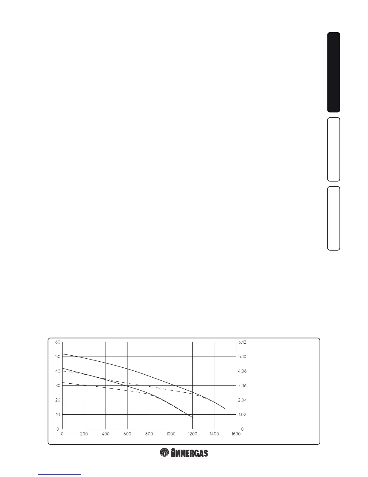
By-pass regulation (part. 24 Fig. 1-33). If neces-
sary, the by-pass can be regulated according to
plant requirements from a minimum (by-pass
excluded) to a maximum (by-pass inserted)
represented by the following graphics (Fig. 1-32).
Make the regulation using a at head screwdriver,
turn clockwise and insert the by-pass, anti-
clockwise it is excluded.
Head (m H
2
O)
Flow rate (l/h)
Head (kPa)
Total head available to the plant.
A = Head available to the system
at maximum speed with by-
pass excluded.
B = Head available to the system
at maximum speed with by-
pass inserted.
C = Head available to the system
at second speed with by-pass
excluded.
D = Head available to the system
at second speed with by-pass
inserted.