24 - IE
INSTALLATORUSERTECHNICIAN
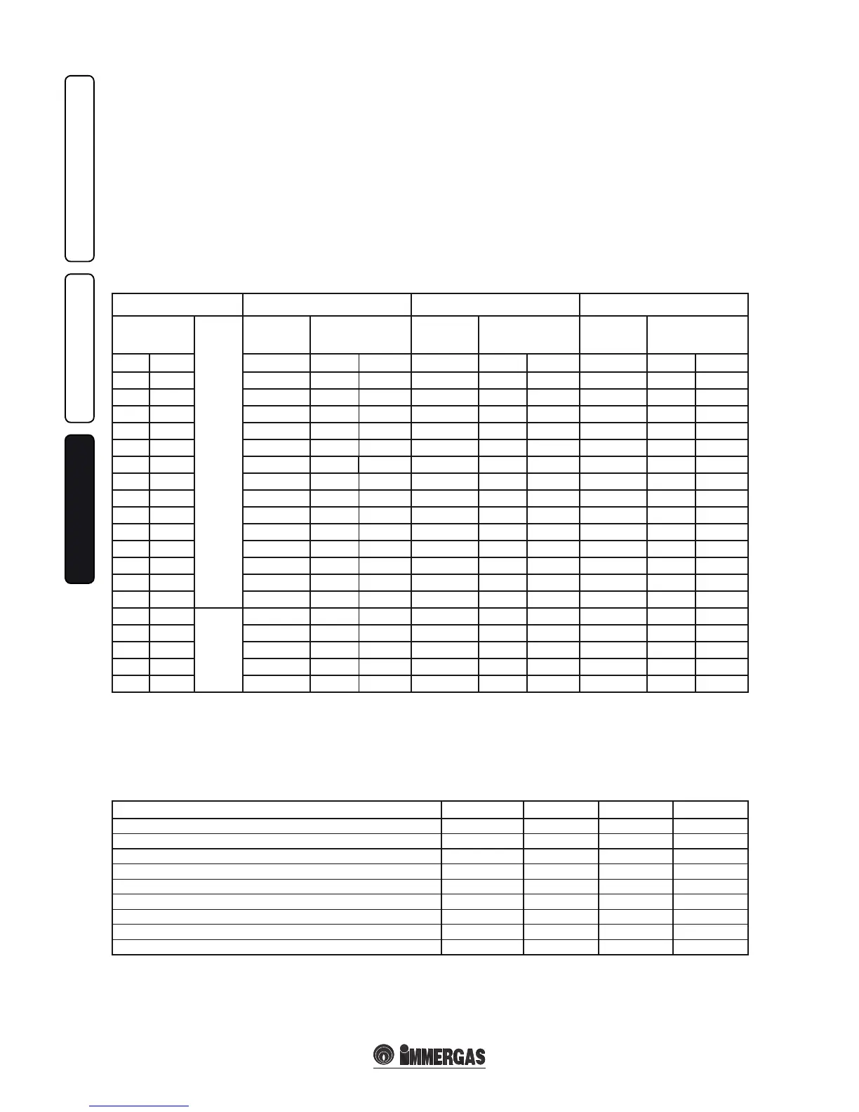
METHANE (G20) BUTANE (G30) PROPANE (G31)
HEATING
POWER
H
E
A
T
I
N
G
+
DOME
STIC
HOT
WATER.
BURNER
GAS FLOW
RATE
PRESS. BURNER
NOZZLES
BURNER
GAS FLOW
RATE
PRESS. BURNER
NOZZLES
BURNER
GAS FLOW
RATE
PRESS. BURNER
NOZZLES
(kW) (kcal/h) (m
3
/h) (mbar) (mm H
2
O) (kg/h) (mbar) (mm H
2
O) (kg/h) (mbar) (mm H
2
O)
23,8 20468 2,70 11,40 116,3 2,01 28,20 287,6 1,98 36,30 370,2
23,0 19780 2,61 10,65 108,6 1,94 26,30 268,2 1,91 33,97 346,4
21,9 18806 2,48 9,65 98,4 1,85 23,76 242,3 1,82 30,84 314,5
21,0 18060 2,38 8,92 91,0 1,78 21,93 223,6 1,75 28,58 291,5
20,0 17200 2,27 8,13 82,9 1,70 19,94 203,3 1,67 26,11 266,2
19,0 16340 2,16 7,39 75,3 1,61 18,07 184,3 1,59 23,77 242,4
18,0 15480 2,06 6,69 68,2 1,53 16,31 166,3 1,51 21,56 219,8
17,0 14620 1,95 6,02 61,4 1,45 14,65 149,4 1,43 19,46 198,5
16,0 13760 1,84 5,40 55,1 1,37 13,10 133,6 1,35 17,48 178,3
15,0 12900 1,74 4,82 49,1 1,30 11,65 118,8 1,27 15,61 159,2
14,0 12040 1,63 4,27 43,5 1,22 10,28 104,9 1,20 13,85 141,2
13,0 11180 1,52 3,75 38,3 1,14 9,01 91,9 1,12 12,18 124,3
12,0 10320 1,42 3,27 33,4 1,06 7,83 79,9 1,04 10,62 108,3
11,5 9847 1,36 3,03 30,9 1,01 7,24 73,8 1,00 9,82 100,2
10,0 8600
DOME
STIC
HOT
WATER.
1,19 2,36 24,1 0,89 5,62 57,3 0,87 7,62 77,7
9,0 7740 1,07 1,95 19,9 0,80 4,64 47,3 0,78 6,25 63,7
8,0 6880 0,95 1,59 16,3 0,71 3,79 38,6 0,70 5,02 51,2
7,0 6020 0,83 1,27 13,0 0,62 3,04 31,0 0,61 3,91 39,9
6,8 5848 0,81 1,22 12,4 0,60 2,91 29,7 0,59 3,71 37,8
3.17 VARIABLE HEAT POWER.
N.B.: the pressures indicated in the table repre-
sent the dierence in existing pressures between
the gas valve outlet and the combustion chamber.
e adjustments should therefore, be carried
out using a dierential manometer (small “U”-
shaped column or digital manometer) with the
probes inserted in the pressure test gas valve
outlet and on the sealed chamber positive pres-
sure test. e power data in the table has been
obtained with intake-exhaust pipe measuring 0.5
m in length. Gas ow rates refer to heating power
below a temperature of 15°C and at a pressure of
1013 mbar. Burner pressure values refer to use
of gas at 15°C.
3.18 COMBUSTION PARAMETERS.
G20 G30 G31
Gas nozzle diameter mm 1,35 0,79 0,79
supply pressure mbar (mm H
2
O) 20 (204) 29 (296) 37 (377)
Mass ow of fumes at nominal power kg/h 53 53 55
Mass ow of fumes at min. power kg/h 52 53 54
CO
2
at Q. Nom./Min. % 6,95 / 1,95 8,00 / 2,24 7,66 / 2,20
CO at 0% di O
2
at Q. Nom./Min. ppm 79 / 140 95 / 147 63 / 137
NO
X
at 0% di O
2
at Q. Nom./Min. ppm 55 / 34 77 / 30 78 / 30
Temperature of fumes at nominal output °C 110 112 109
Temperature of fumes at minimum output °C 96 93 95