C12
1-15
C12
C12
C12
C12
1-16
1-18
1-19
1-17
1
3
2
4
5
9 - IE
INSTALLATORUSERTECHNICIAN
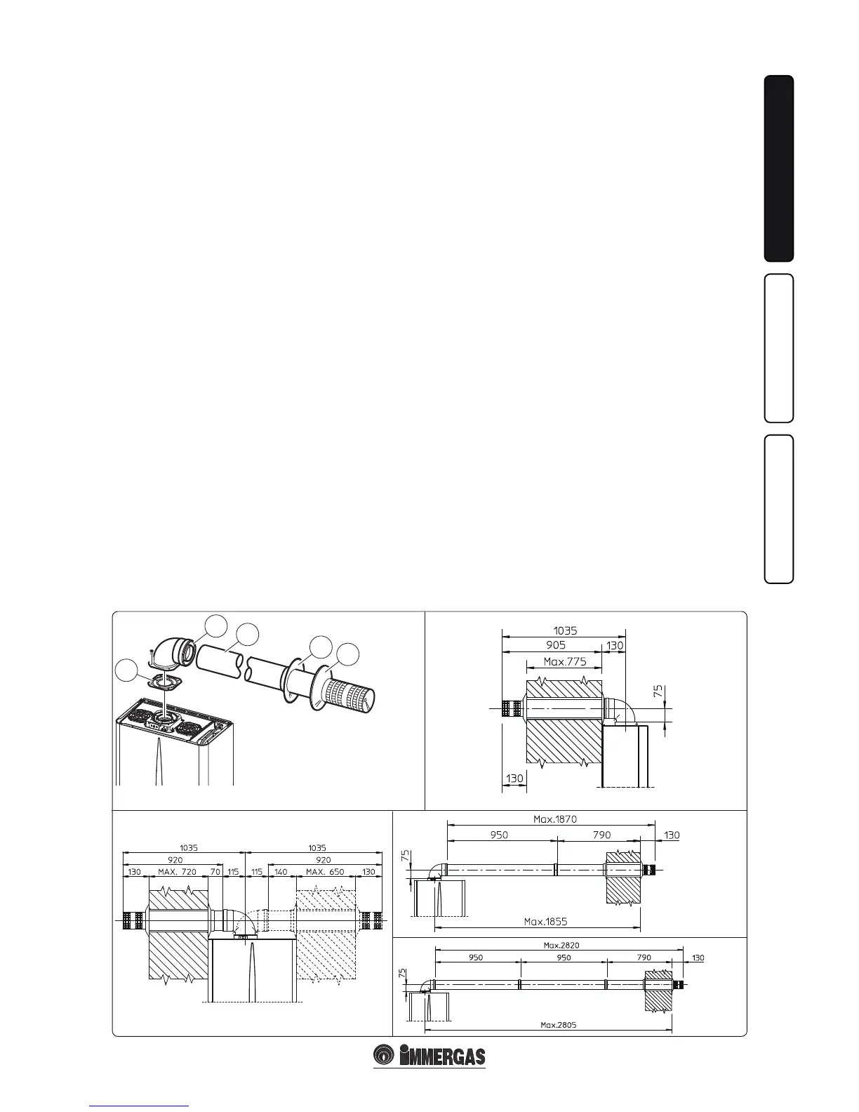
1.10 INDOOR INSTALLATION.
• Type C conguration, sealed chamber and
forced draught.
Horizontal intake - exhaust kit Ø60/100. Kit
assembly (Fig. 1-15): install the bend with ange
(2) on the central hole of the boiler inserting the
gasket (1) and tighten using the screws in the kit.
Couple the terminal pipe (3) with the male end
(smooth) into the female end of the bend (with
lip seals) up to the stop; making sure that the in-
ternal wall sealing plate and external wall sealing
plate have been tted, this will ensure sealing
and joining of the elements making up the kit.
Note: when the boiler is installed in areas where
very rigid temperatures can be reached, a special
anti-freeze kit is available that can be installed as
an alternative to the standard kit.
• Coupling extension pipes and concentric
elbows Ø 60/100. To snap-t extensions with
other elements of the fume extraction elements,
operate as follows Install the concentric pipe
or elbow with the male side (smooth) on the
female section (with lip seal) to the end stop
on the previously installed element. is will
ensure the sealing and joining of the elements
correctly.
e Ø 60/100 horizontal intake/exhaust kit can
be installed with the rear, right side, le side and
front outlet.
• Application with rear outlet (Fig. 1-16). e
970 mm pipe length enables routing through
a maximum thickness of 775 mm. Normally
the terminal must be shortened. Calculate
the distance by adding the following values:
Part thickness + internal projection + exter-
nal projection. e minimum indispensable
projection values are given in the gure.
• Application with side outlet (Fig. 1-17); Using
the horizontal intake-exhaust kit, without the
special extensions, enables routing through
a wall thickness of 720 mm with the le side
outlet and 650 with the right side outlet.
• Extensions for horizontal kit. e horizontal
intake-exhaust kit Ø 60/100 can be extended
up to a max. horizontal distance of 3,000 mm
including the terminal with grid and excluding
the concentric bend leaving the boiler. is
conguration corresponds to a resistance factor
of 100. In these cases the special extensions
must be requested.
Connection with N°1 extension (Fig. 1-18).
Max. distance between vertical boiler axis and
external wall is 1855mm.
Connection with N°2 extensions (Fig. 1-19).
Max. distance between vertical boiler axis and
external wall is 2805mm.
Horizontal intake-exhaust kit Ø 80/125 Kit
assembly (Fig. 1-20): install the bend with ange
(2) onto the central hole of the boiler inserting
the gasket (1) and tighten using the screws in the
kit. Fit the male end (smooth) of the adapter (3)
up to the stop on the female end of the bend (2)
(with lip seal). Fit the Ø 80/125 (4) concentric
terminal pipe with the male end (smooth) to the
female end of the adapter (3) (with lip gasket) up
to the stop; making sure that the internal wall
sealing plate and external wall sealing plate have
been tted, this will ensure sealing and joining
of the elements making up the kit.
• Coupling extension pipes and concentric
elbows Ø 80/125. To snap-t extensions with
other elements of the fume extraction elements,
operate as follows Install the concentric pipe
or elbow with the male side (smooth) on the
female section (with lip seal) to the end stop
on the previously installed element. is will
ensure sealing and joining of the elements
correctly.
Important: if the exhaust terminal and/or exten-
sion concentric pipe needs shortening, consider
that the internal duct must always protrude by 5
mm with respect to the external duct.
Normally the Ø 80/125 horizontal intake-exhaust
kit is used if particularly long extensions are re-
quired; the Ø 80/125 kit can be installed with the
rear, right side, le side or front outlet.
• Extensions for horizontal kit. e Ø 80/125
horizontal intake-exhaust kit can be extended
up to a max. horizontal distance of 7,300 mm
including the terminal with grid and excluding
the concentric bend leaving the boiler and the
adapter Ø 60/100 in Ø 80/125 (Fig. 1-21). is
conguration corresponds to a resistance factor
of 100. In these cases the special extensions
must be requested.
N.B.: when installing the pipes, a section clamp
with pin must be installed every 3 metres.
• External grill. N.B.: for safety purposes, do not
even temporarily obstruct the boiler intake-
exhaust terminal.
e kit includes:
N°1 - Gasket (1)
N°1 - Concentric bend 90° (2)
N°1 - Intake-exhaust concentric pipe
Ø60/100 (3)
N°1 - Internal white wall sealing plate (4)
N°1 - External grey wall sealing plate (5)