C32
1-241-23
C32
C12
1-20
C12
1-21
1
3
2
5
6
4
1
2
3
4
6
5
7
8
10 - IE
INSTALLATORUSERTECHNICIAN
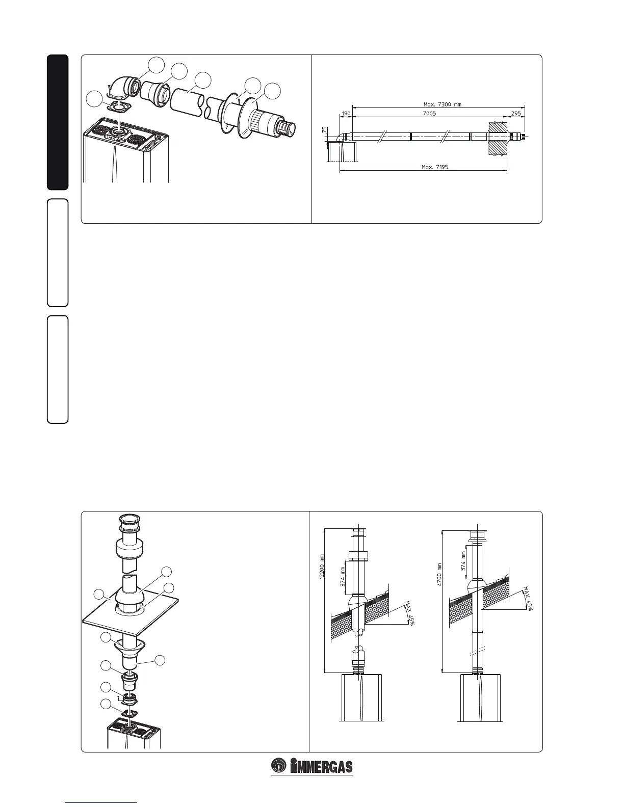
Vertical kit with aluminium tile Ø 80/125. Kit
assembly (Fig. 1-23): install the concentric ange
(2) on the central hole of the boiler inserting the
gasket (1) and tighten using the screws in the
kit. Fit the male end (smooth) of the adapter (3)
into the female end of the concentric ange (2).
Imitation aluminium tile installation. Replace the
tile with the aluminium sheet (5), shaping it to
ensure that rainwater runs o. Position the xed
half-shell (7) and insert the intake-exhaust pipe
(6). Fit the Ø 80/125 concentric terminal pipe
with the male end (6) (smooth) to the female end
of the adapter (3) (with lip gasket) up to the stop;
making sure that the wall sealing plate has been
tted, this will ensure sealing and joining of the
elements making up the kit.
• Coupling extension pipes and concentric el-
bows. To install snap-t extensions with other
elements of the fume extraction elements as-
sembly, proceed as follows: Install the concen-
tric pipe or elbow with the male side (smooth)
on the female section (with lip seal) to the end
stop on the previously installed element. is
will ensure sealing and joining of the elements
correctly.
Important: if the exhaust terminal and/or exten-
sion concentric pipe needs shortening, consider
that the internal pipe must always protrude by 5
mm with respect to the external pipe.
is specic terminal enables ue exhaust and
air intake, necessary for combustion, in a vertical
direction.
N.B.: e Ø 80/125 vertical kit with aluminium
tile enables installation on terraces and roofs with
a maximum slope of 45% (24°) and the height
between the terminal cap and half-shell (374
mm) must always be respected.
e vertical kit with this conguration can be
extended up to a maximum of 12200 mm vertical
rectilinear, with the terminal included (Fig. 1-24).
is conguration corresponds to a resistance
factor of 100. In this case the special extensions
must be requested.
The terminal Ø 60/100 can also be used for
vertical exhaust, in conjunction with concentric
flange code 3.011141 (sold separately). The
height between the terminal cap and half-shell
(374 mm) must always be respected (Fig. 1-24).
e vertical kit with this conguration can be
extended up to a maximum of 4700 mm vertical
rectilinear, with the terminal included (Fig. 1-24).
Separator kit Ø 80/80. e Ø 80/80 separator
kit, allows separation of the exhaust ues and
air intake pipes according to the diagram shown
in the gure. Combustion products are expelled
from pipe (S). Air is taken in through pipe (A)
for combustion. The intake pipe (A) can be
installed either on the right or le hand side of
the central exhaust pipe (S). Both ducts can be
routed in any direction.
• Kit assembly (Fig. 1-25): install ange (4) on
the central hole of the boiler, tting the gasket
(1), and tighten with the at-tipped hex screws
included in the kit. Remove the flat flange
present in the lateral hole with respect to the
central one (according to needs) and replace it
with the ange (3), positioning the gasket (2)
already present in the boiler and tighten using
the supplied self-threading screws. Fit the male
end (smooth) to the bends (5) in the female end
of the anges (3 and 4). Fit the intake terminal
(6) with the male section (smooth) in the
female section of the bend (5) to the end stop,
ensuring that the internal and external rings are
tted. Fit the exhaust pipe (9) with the male end
(smooth) to the female end of the bend (5) up
to the stop; making sure that the internal wall
sealing plate has been tted. is will ensure
sealing and joining of the elements making up
the kit.
e kit includes:
N°1 - Gasket (1)
N°1 - Concentric bend Ø 60/100 (2)
N°1 - Adapter Ø 60/100 for Ø 80/125 (3)
N°1 - Concentric intake-exhaust terminal
Ø 80/125 (4)
N°1 - Internal white wall sealing plate (5)
N°1 - External grey wall sealing plate (6)
e kit includes:
N°1 - Gasket (1)
N°1 - Female concentric ange (2)
N°1 - Adapter Ø 60/100 for Ø 80/125 (3)
N°1 - Wall sealing plate (4)
N°1 - Aluminium tile (5)
N°1 - Concentric intake-exhaust terminal
Ø 80/125 (6)
N°1 - Fixed half-shell
N°1 - Mobile half-shell
MAXIMUM LENGTH
MAXIMUM LENGTH