C82
1-25
C42
C52
1-26
1-28
C82
1-27
4
6
5
1
3
2
7
8
5
9
7
A
S
11 - IE
INSTALLATORUSERTECHNICIAN
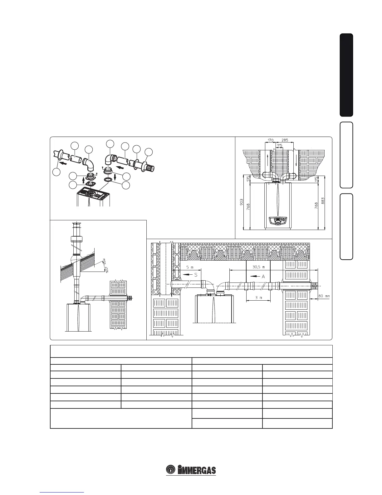
• Coupling of extension pipes and elbows. To
install snap-t extensions with other elements
of the fume extraction elements assembly, pro-
ceed as follows: Install the pipe or elbow with
the male side (smooth) on the female section
(with lip seal) to the end stop on the previously
installed element. is will ensure sealing and
joining of the elements correctly.
• Figure 1-27 shows the configuration with
vertical exhaust and horizontal intake.
• Installation clearances. Figure 1-26 gives the
min. installation space dimensions of the Ø
80/80 separator terminal kit in limited condi-
tions.
• Extensions for the separator kit Ø 80/80. e
max. vertical straight length (without bends)
that can be used for Ø 80 intake and exhaust
pipes is 41 metres of which 40 intake and 1
exhaust. The total length corresponds to a
resistance factor of 100. e total usable length
obtained by adding the length of the intake and
exhaust pipes Ø 80 must not exceed the values
stated in the following table. If mixed accessori-
es or components are used (e.g. changing from
a separator Ø 80/80 to a concentric pipe), the
maximum extension can be calculated by using
a resistance factor for each component or the
equivalent length. e sum of these resistance
factors must not exceed 100.
• Temperature loss in fume ducts. To prevent
problems of fume condensate in the exhaust
pipe Ø 80, due to fume cooling through the
wall, the length of the pipe must be limited to
just 5 m. Fig. 1-28). If longer distances must
be covered, use Ø 80 pipes with insulation (see
insulated separator kit Ø 80/80 chapter).
N.B.: when installing the Ø 80 ducts, a section
clamp with pin must be installed every 3 metres.
* e air intake pipe can be increased to 2.5
metres if the exhaust bend is eliminated, 2
metres if the air intake bend is eliminated, and
4.5 metres eliminating both bends.
e kit includes:
N°1 - Exhaust gasket (1)
N°1 - Female intake ange (3)
N°1 - Flange gasket (2)
N°1 - Female exhaust ange (4)
N°2 - 90° bend Ø 80 (5)
N°1 - Intake terminal Ø 80 (6)
N°2 - Internal white wall sealing plates (7)
N°1 - External grey wall sealing ring (8)
N°1 - Exhaust pipe Ø 80 (9)
Maximum usable length
(including intake terminal with grill and two 90° bends)
NON INSULATED PIPE INSULATED PIPE
Exhaust (m) Intake (m) Exhaust (m) Intake (m)
1 36,0* 6 29,5*
2 34,5* 7 28,0*
3 33,0* 8 26,5*
4 32,0* 9 25,5*
5 30,5* 10 24,0*
* e air intake pipe can be increased to 2.5 metres if the exhaust bend is
eliminated, 2 metres if the air intake bend is eliminated, and 4.5 metres
eliminating both bends.
11 22,5*
12 21,5*
Important: the boiler was designed to evacuate
combustion product up to a maximum extension
of 27 linear m to the exhaust, with 1 m plus 90°
bend at intake. If installation requires an exten-
sion of the ue ttings up to the exhaust that
exceeds the 12 m recommended, it is necessary
to properly consider the possibility that conden-
sation may form inside the duct and therefore
Immergas “Serie Blu” insulated ue ttings, or
other ue ttings with similar characteristics,
should be used.