1-30
1-31
1-29
5
4
1
3
2
5
6
7
8
8
10
11
9
S
A
C82
C82C82
12 - IE
INSTALLATORUSERTECHNICIAN
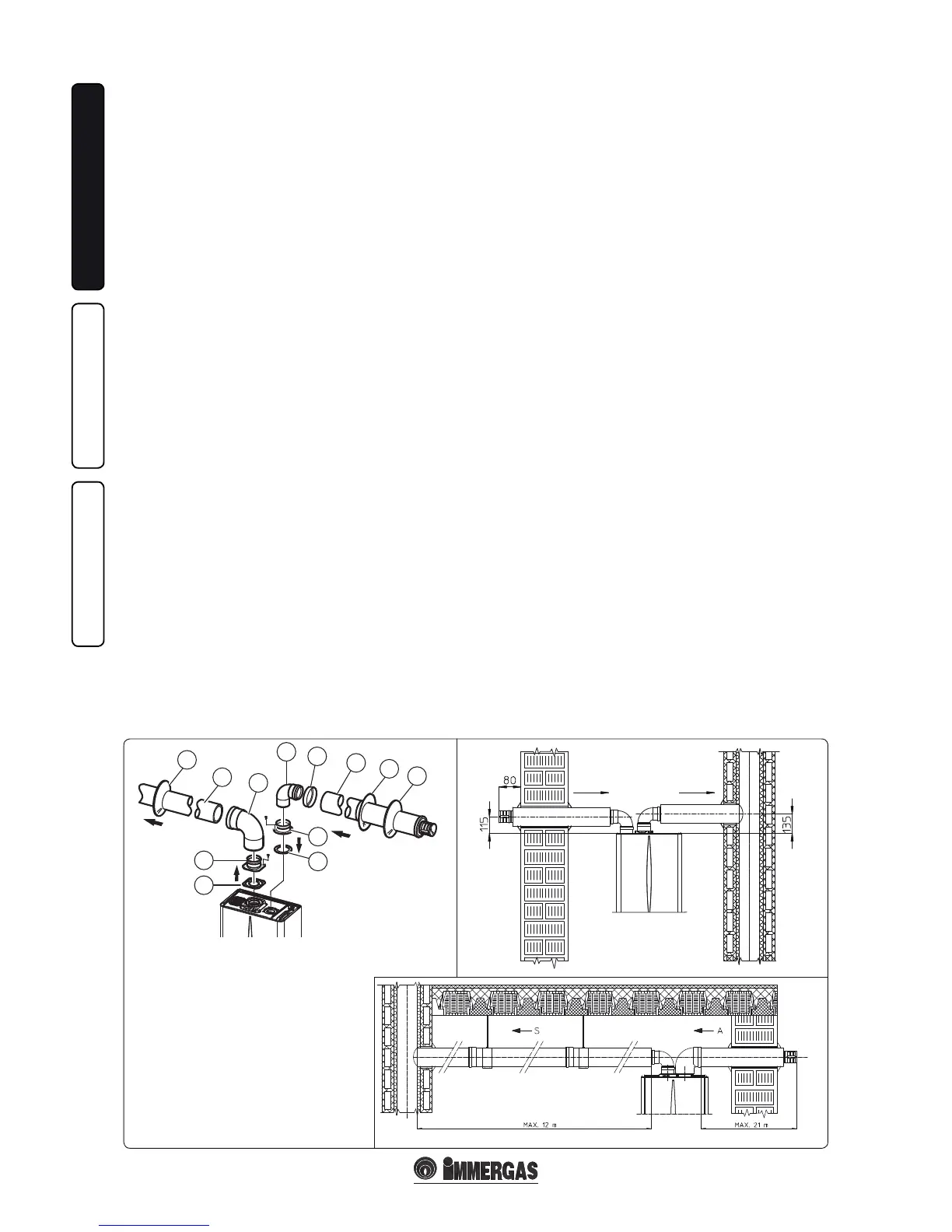
Insulated separator kit Ø 80/80. Kit assembly
(Fig. 1-29): install ange (4) on the central hole
of the boiler, tting gasket (1) and tighten with
the at-tipped hex screws included in the kit.
Remove the at ange present in the lateral hole
with respect to the central one (according to ne-
eds) and replace it with the ange (3), positioning
the gasket (2) already present in the boiler and
tighten using the supplied self-threading screws.
Insert and slide cap (6) onto bend (5) from the
male side (smooth), and join bends (5) with the
male side (smooth) in the female side of ange
(3). Fit bend (11) with the male side (smooth)
into the female side of ange (4). Fit the male
end (smooth) of the intake terminal (7) up to the
stop on the female end of the bend (5), making
sure you have already inserted the wall sealing
plates (8 and 9) that ensure correct installation
between pipe and wall, then x the closing cap
(6) on the terminal (7). Join the exhaust pipe (10)
with the male side (smooth) in the female side
of the bend (11) to the end stop, ensuring that
the wall sealing plate (8) is already inserted for
correct installation between the pipe and ue.
• Coupling extension pipes and elbows.
To snap-t extensions with other elements of
the fume extraction elements, operate as fol-
lows: Install the concentric pipe or elbow with
the male side (smooth) on the female section
(with lip seal) to the end stop on the previously
installed element. is will ensure sealing and
joining of the elements correctly.
• Insulation of separator terminal kit. In case of
problems of fume condensate in the exhaust pi-
pes or on the outside of intake pipes, Immergas
supplies insulated intake and exhaust pipes on
request. Insulation may be necessary on the
exhaust pipe due to excessive temperature loss
of fumes during conveyance. Insulation may be
necessary on the intake pipe as the air entering
(if very cold) may cause the outside of the pipe
to fall below the dew point of the environmen-
tal air. e gures (Fig. 1-29 and 1-30) illustrate
dierent applications of insulated pipes.
Insulated pipes are formed of a Ø 80 internal
concentric pipe and a Ø 125 external pipe with
static air space. It is not technically possible
to start with both Ø 80 elbows insulated, as
clearances will not allow it. However starting
with an insulated elbow is possible by choosing
either the intake or exhaust pipe. When star-
ting with an insulated intake bend, it must be
inserted onto its ange up to the stop on the
fume exhaust ange, which will ensure that the
two intake and exhaust outlets are at the same
height.
• Temperature loss in insulated fume ducting.
To prevent problems of fume condensate in
the exhaust pipe Ø 80, due to fume cooling
through the wall, the length of the pipe must
be limited to 12 m. e gure (Fig. 1-31) illu-
strates a typical insulation application in which
the intake pipe is short and the exhaust pipe is
very long (over 5 m). e entire intake pipe is
insulated to prevent moist air in the place where
the boiler is installed, in contact with the pipe
cooled by air entering from the outside. e
entire exhaust pipe, except the elbow leaving
the splitter is insulated to reduce heat loss from
the pipe, thus preventing the formation of fume
condensate.
N.B.: When installing the ducts, a section
clamp with pin must be installed every 2 me-
tres.
• Conguration type B, open chamber and
forced draught.
When using type B installation conguration
indoors, it is compulsory to install the relative up-
per cover kit along with the fumes discharge kit.
e air intake comes directly from the area where
the boiler is installed and from the ue exhaust
in each single ue or directly from outdoors.
e boiler in this conguration, following the
assembly instructions on pages 8 and 9, is clas-
sied as type B.
With this conguration:
- air intake takes place directly from the environ-
ment in which the boiler is installed and only
functions in permanently ventilated rooms;
- the ue exhaust must be connected to its own
individual ue or channelled directly into the
external atmosphere.
- Type B open chamber boilers must not be
installed in places where commercial, artisan
or industrial activities take place, which use
products that may develop volatile vapours
or substances (e.g. acid vapours, glues, paints,
solvents, combustibles, etc.), as well as dusts
(e.g. dust deriving from the working of wood,
coal nes, cement, etc.), which may be dama-
ging for the components of the appliance and
jeopardise functioning.
When using type B installation conguration
indoors, it is compulsory to install the relative up-
per cover kit along with the fumes discharge kit.
The technical regulations in force must be
respected.
e kit includes:
N°1 - Exhaust gasket (1)
N°1 - Flange seal (2)
N°1 - Female intake ange (3)
N°1 - Female exhaust ange (4)
N°1 - Bend 90° Ø 80 (5)
N°1 - Pipe closure cap (6)
N°1 - Intake terminal Ø 80 insulated (7)
N°2 - Internal white wall sealing plates (8)
N°1 - External grey wall sealing plate (9)
N°1 - Discharge pipe Ø 80 insulated (10)
N°1 - Concentric bend 90° Ø 80/125 (11)