1-11
1-10
1-13
1-14
1-12
1-9
7 - IE
INSTALLATORUSERTECHNICIAN
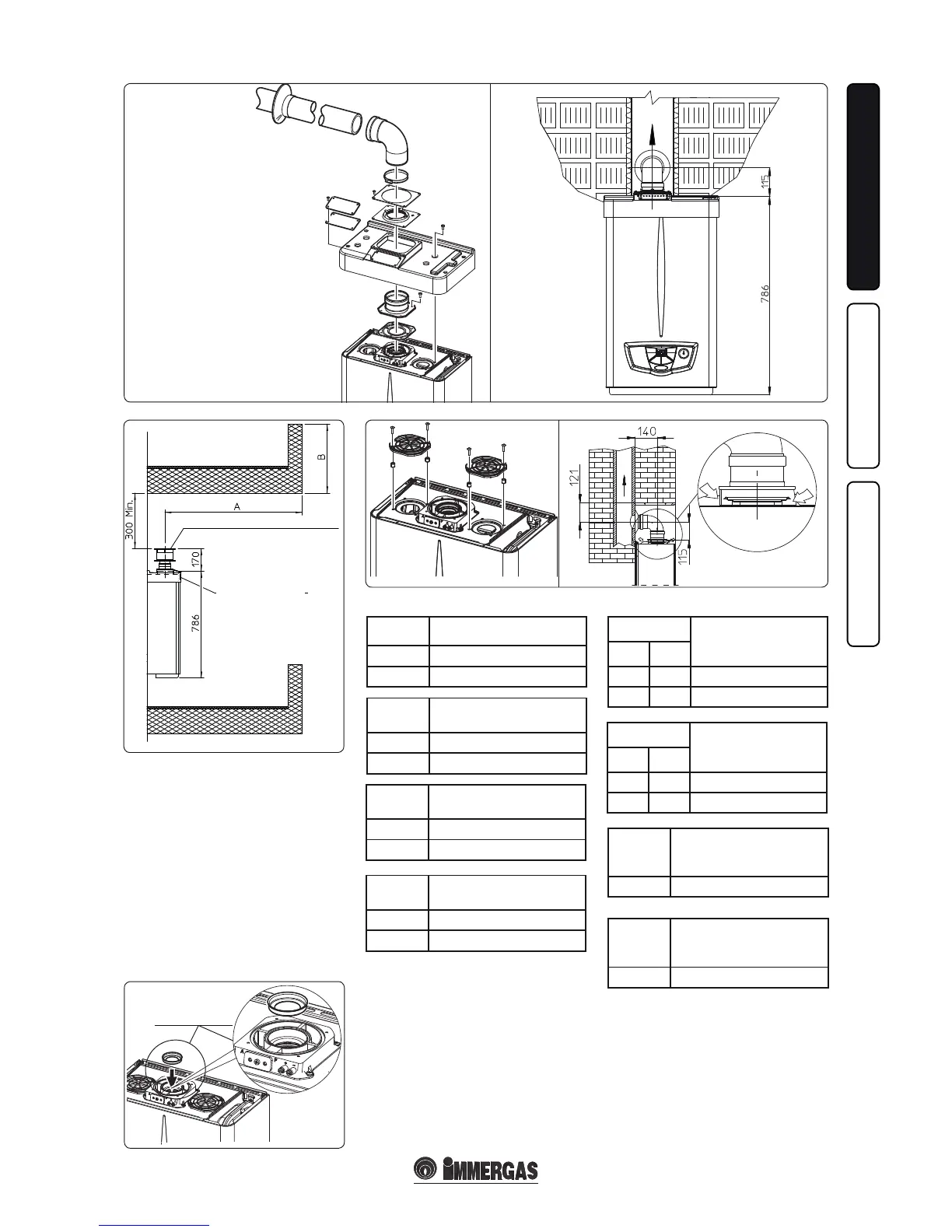
Diaphragm installation. For correct functio-
ning of the boiler it is necessary to install a dia-
phragm on the outlet of the sealed chamber and
before the intake and exhaust pipe (Fig. 1-14).
e choice of suitable diaphragm takes place on
the basis of the type of pipe and its maximum
extension: this calculation can be carried out
using the following tables:
N.B.: the diaphragms are supplied together with
the boiler.
VERTICAL TERMINAL KIT FOR DIRECT DRAINING
INTAKE COVER KIT
DIAPHRAGM
Diaphragm
Extension in meters
pipe Ø 60/100 horizontal
Ø 38 From 0 to 1
Ø 42.5 Exceeding 1
Diaphragm
Pipe extension in metres Ø
60/100 vertical
Ø 38 From 0 to 3.2
Ø 42.5 Exceeding 3.2
Diaphragm
Pipe extension in metres Ø
80/125 horizontal
Ø 38 From 0 to 3.3
Ø 42.5 Exceeding 3.3
Diaphragm
Pipe extension in metres Ø
80/125 vertical
Ø 38 From 0 to 8.1
Ø 42.5 Exceeding 8.1
Diaphragm
*Extension in metres
vertical pipe Ø 80
without bends
exhaust intake
- Ø 45 From 0 to 18
Ø 42.5 - From 14 to 40
Diaphragm
*Extension in metres
horizontal pipe Ø 80
with two bends
exhaust intake
- Ø 45 From 0 to 14
Ø 42.5 - From 14 to 35
Diaphragm
intake
**Extension in metres
horizontal pipe Ø 80 with
two bends
Ø 45 From 0 to 27
Diaphragm
intake
**Extension in metres
vertical pipe Ø 80
without bends
Ø 45 From 0 to 27
* ese maximum extension values are considered
intake with 1 metre drain pipe.
** ese maximum extension values are considered
exhaust with 1 metre intake pipe.