16
3-2
INSTALLERUSER
MAINTENANCE TECHNICIAN
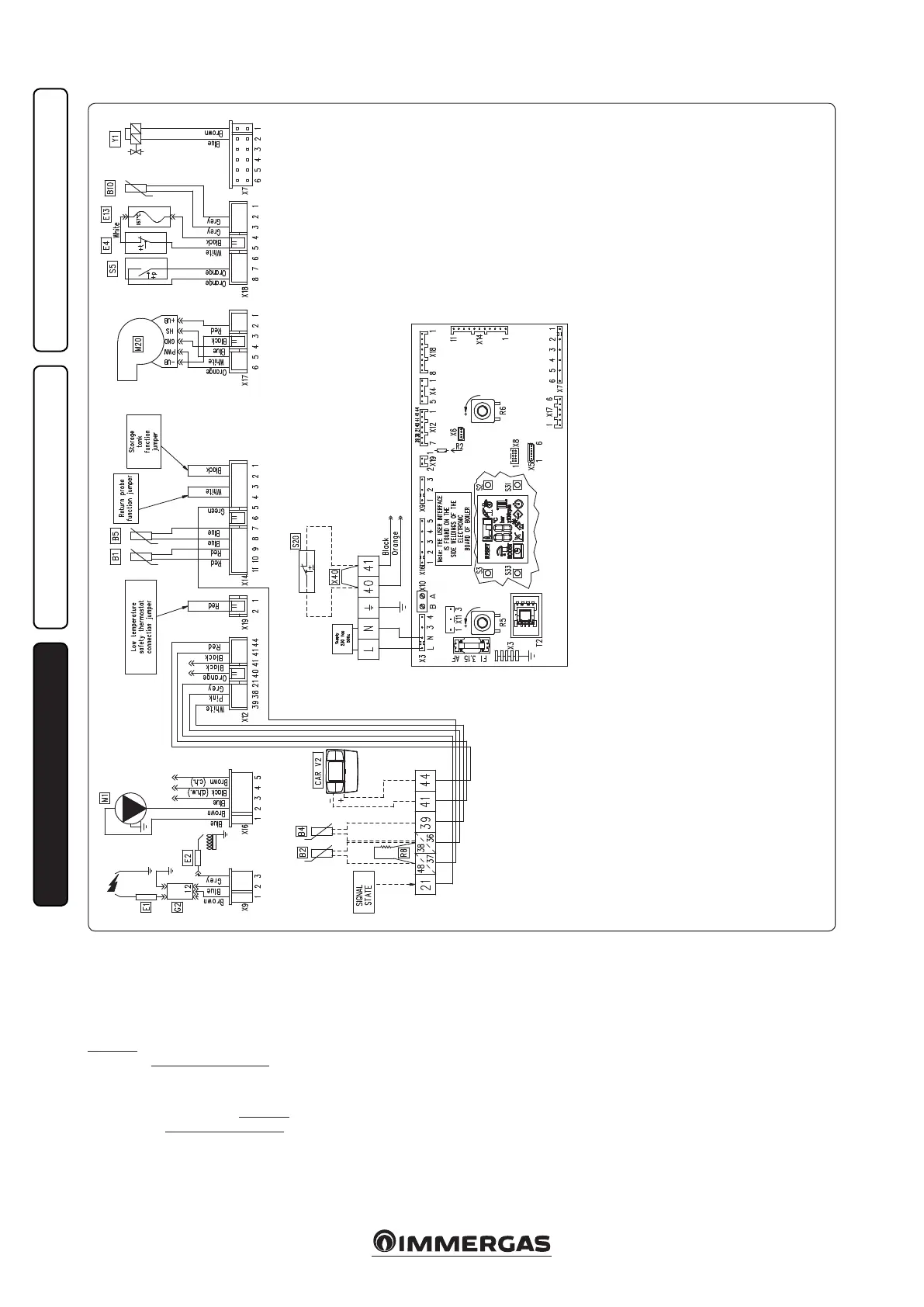
3.2 WIRING DIAGRAM.
Storage tank unit: the boiler is prepared for the
connection to a storage tank unit, which must
be connected to clamps 36 - 37 of the terminal
board, eliminating resistance R8.
CAR
V2
: the boiler is prepared for the application
of the CAR
V2
(which must be connected to clamps
41 and 44 of the terminal board respecting the
polarity and eliminating jumper X40.
Room thermostat: the boiler is prepared for the
application of the room thermostat (S20), which
must be connected to clamps 40 and 41 of the
terminal board eliminating jumper X40.
e connector X5 is used for the connection to
the relay P.C.B..
e connector X6 is used for the connection to
the personal computer.
e connector X8 is used for soware updating
operations.
Key:
B1 - Flow probe
B2 - Domestic hot water probe (optional)
B4 - External probe (optional)
B5 - Return probe
B10 - Flue probe
CAR
V2
- Comando Amico Remoto
Version 2
remote control (optional)
E1 - Ignition electrode
E2 - Detection electrode
E4 - Overheating safety thermostat
E13 - Exchanger safety thermofuse
G2 - Igniter
M1 - Boiler pump
M20 - Fan
R5 - Trimmer DHW set
R6 - Trimmer CH set
R8 - Storage tank inhibition resistor
S2 - Functioning knob
S3 - Reset button
S5 - System pressure switch
S20 - Room thermostat (optional)
S31 - On/Stand-by/O button
S33 - Info button
T2 - Voltage transformer
X40 - Room thermostat jumper
Y1 - Gas valve