4
1-1
M
P
D
W
I
j
j
j
h
h
k
k
h
f
c
a
c
e
e
d
k
g
T
b
T
g
T
INSTALLERUSER
MAINTENANCE TECHNICIAN
1
BOILER
INSTALLATION
1.1 INSTALLATION
RECOMMENDATIONS.
e INTEC 12-30 SYSTEM EXTERNAL boiler
has been designed uniquely for wall-installation,
for the heating of rooms for domestic use.
- installation (according to the legislation and
technical standards in force);
- maintenance operations (including those
scheduled, periodical, ordinary and special);
- removal (to the outdoors in a place suitable
for loading and transporting appliances and
components) as well as any replacement with
equivalent appliances and/or components.
e wall surface must be smooth, without any
protrusions or recesses enabling access to the
rear part. ey are not designed to be installed
on plinths or oors (Fig. 1-1).
By varying the type of installation the
classication of the boiler also varies, precisely:
- Type C boiler Uses concentric or Coaxial pipes
systems Hunt Heating supplies the correct ue
for this application.
Only professionally heating/plumbing
technicians are authorised to install Immergas
gas appliances.
Installation must be carried out according to
regulation standards AS/NZS 5601 or Local
Authority laws.
Installation of the INTEC 12-30 SYSTEM
EXTERNAL boiler when powered by Universal
LPG must also comply with the rules regarding
gases with a greater density and be installed
to meet all local and AS/NZS 5601 LAWS.
Before installing the appliance, ensure that it
is delivered in perfect condition; if in doubt,
contact the supplier immediately. Packing
materials (staples, nails, plastic bags, polystyrene
foam, etc.) constitute a hazard and must be kept
out of the reach of children. Leave adequate
space above the boiler for possible water and
ue removal connections. Keep all ammable
objects away from the appliance (paper, rags,
plastic, polystyrene, etc.). Do not place household
appliances underneath the boiler as they could
be damaged if the safety valve intervenes (if not
conveyed away by a draining funnel), or if there
are leaks from the connections; on the contrary,
the manufacturer cannot be held responsible for
any damage caused to the household appliances.
In the event of malfunctions, faults or incorrect
operation, turn the appliance o immediately and
contact a qualied technician (e.g. Hunt Heating
Service Dept which has specically trained sta
and original spare parts). Do not attempt to
modify or repair the appliance alone.
Failure to comply with the above implies personal
responsibility and invalidates the warranty.
Installation Standards:
- Installations MUST comply with AS/NZS
5601 and Local laws. Use AS/NZS 5601 as
a guide for specic locations see below.
- Installation is prohibited on the vertical
projection of the cooking surface.
- Installation is also prohibited in places/
environments that constitute common parts
of oce condominiums such as stairs, cellars,
entrance halls, attics, los, escape routes,
etc. if they are not located inside technical
compartments under the responsibility of
each individual building and only accessible
to the user (for the features of the technical
compartments, see the technical standards in
force).
YES NO
Attention: wall mounting of the boiler must
guarantee stable and ecient support for the
boiler.
Use the bracket supplied as standard, xing it
with proper plugs according to the wall type. e
installer is responsible for the choose of the correct
plugs, according to the technical standard. Place
the supplied bracket, following the indications
reported on drawing 1-3 preferring the holes
indicated in the before mentioned draw.
N.B.: to fix the bracket we suggest to use
hexagon screw or countersunk screw for plug.
ese boilers are used to heat water to below
boiling temperature in atmospheric pressure.
ey must be attached to a heating system suit-
able for their capacity and voltage.
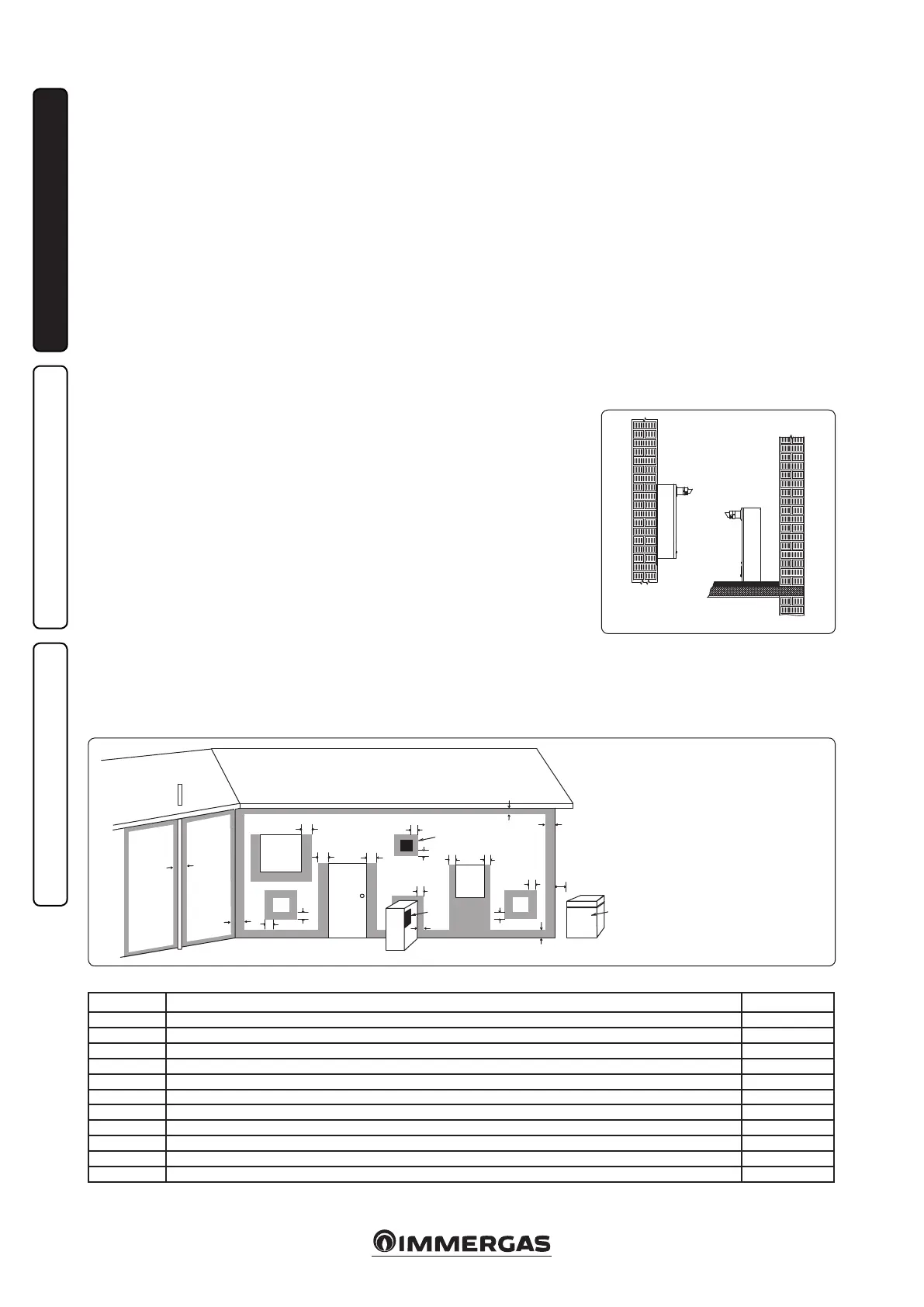
1-2
Flue terminal positions
Use as a guide only. Refer to AS/NZS 5601 or gas tting rules for specic location.
D - Door
I - Mechanical air inlet
M - Gas meter
T - Flue Terminal
W - Window
Ref. Item Min. Clearance mm
a
Below eaves, balconies and other projections (Appliances over 50MJ/h) 300
b
From the ground, above a balcony or other surface 300
c
From a return wall or external wall 300
d
From a gas meter 1000
e
From an electricity meter or fusebox/breaker panel 500
f
From a drain pipe or soil pipe 75
g
Horizontally from any building structure or obstruction facing a ue terminal 500
h
From any other ue terminal, cowl or combustion air intake 300
j
Horizontally from any opening window, door, non-mechanical air inlet or other opening into a building with the exception of sub-oor ventilation 300
k
From a mechanical air inlet including a spa blower 1000
n
Vertically below an opening window, non-mechanical air inlet or any other opening into a building with the exception of sub-oor ventilation 500
• e location of the ue terminal must comply with the clea-
rances shown on this page.
If you are unsure about clearances not indicated here, in general
refer to AS/NZS 5601 or your local autority.
• All measurements are the minimum clearances required.
• Terminals must be positioned so to aviod combustion products
entering the building.
Flue terminal positions. Shaded area indicates prohibited area