12
C12
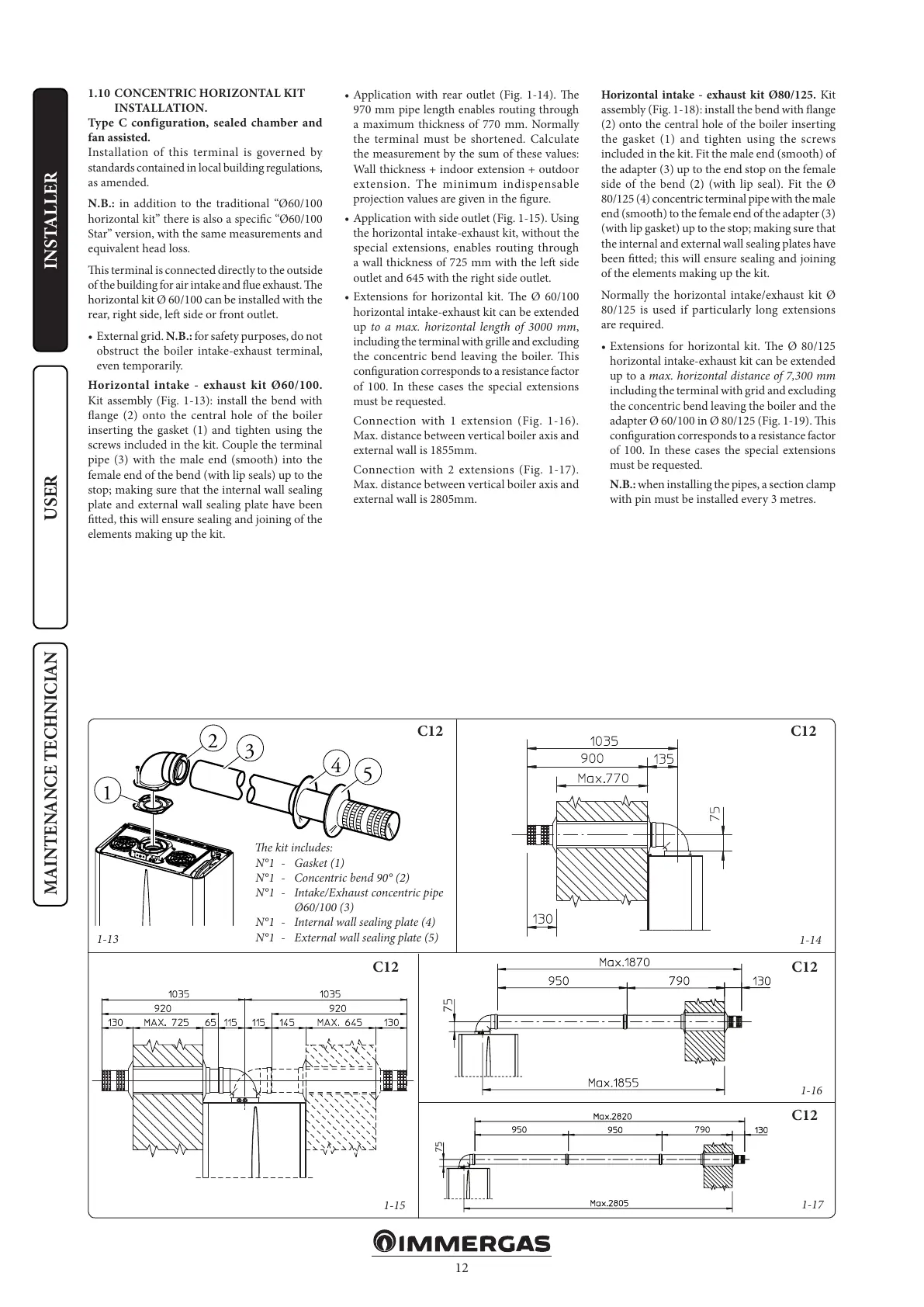
1-13
C12
C12 C12
C12
1-14
1-16
1-17
1-15
1
3
2
4
5
INSTALLERUSER
MAINTENANCE TECHNICIAN
e kit includes:
N°1 - Gasket (1)
N°1 - Concentric bend 90° (2)
N°1 - Intake/Exhaust concentric pipe
Ø60/100 (3)
N°1 - Internal wall sealing plate (4)
N°1 - External wall sealing plate (5)
1.10 CONCENTRIC HORIZONTAL KIT
INSTALLATION.
Type C configuration, sealed chamber and
fan assisted.
Installation of this terminal is governed by
standards contained in local building regulations,
as amended.
N.B.: in addition to the traditional “Ø60/100
horizontal kit” there is also a specic “Ø60/100
Star” version, with the same measurements and
equivalent head loss.
is terminal is connected directly to the outside
of the building for air intake and ue exhaust. e
horizontal kit Ø 60/100 can be installed with the
rear, right side, le side or front outlet.
• External grid. N.B.: for safety purposes, do not
obstruct the boiler intake-exhaust terminal,
even temporarily.
Horizontal intake - exhaust kit Ø60/100.
Kit assembly (Fig. 1-13): install the bend with
ange (2) onto the central hole of the boiler
inserting the gasket (1) and tighten using the
screws included in the kit. Couple the terminal
pipe (3) with the male end (smooth) into the
female end of the bend (with lip seals) up to the
stop; making sure that the internal wall sealing
plate and external wall sealing plate have been
tted, this will ensure sealing and joining of the
elements making up the kit.
• Application with rear outlet (Fig. 1-14). e
970 mm pipe length enables routing through
a maximum thickness of 770 mm. Normally
the terminal must be shortened. Calculate
the measurement by the sum of these values:
Wall thickness + indoor extension + outdoor
extension. The minimum indispensable
projection values are given in the gure.
• Application with side outlet (Fig. 1-15). Using
the horizontal intake-exhaust kit, without the
special extensions, enables routing through
a wall thickness of 725 mm with the le side
outlet and 645 with the right side outlet.
• Extensions for horizontal kit. e Ø 60/100
horizontal intake-exhaust kit can be extended
up to a max. horizontal length of 3000 mm,
including the terminal with grille and excluding
the concentric bend leaving the boiler. is
conguration corresponds to a resistance factor
of 100. In these cases the special extensions
must be requested.
Connection with 1 extension (Fig. 1-16).
Max. distance between vertical boiler axis and
external wall is 1855mm.
Connection with 2 extensions (Fig. 1-17).
Max. distance between vertical boiler axis and
external wall is 2805mm.
Horizontal intake - exhaust kit Ø80/125. Kit
assembly (Fig. 1-18): install the bend with ange
(2) onto the central hole of the boiler inserting
the gasket (1) and tighten using the screws
included in the kit. Fit the male end (smooth) of
the adapter (3) up to the end stop on the female
side of the bend (2) (with lip seal). Fit the Ø
80/125 (4) concentric terminal pipe with the male
end (smooth) to the female end of the adapter (3)
(with lip gasket) up to the stop; making sure that
the internal and external wall sealing plates have
been tted; this will ensure sealing and joining
of the elements making up the kit.
Normally the horizontal intake/exhaust kit Ø
80/125 is used if particularly long extensions
are required.
• Extensions for horizontal kit. e Ø 80/125
horizontal intake-exhaust kit can be extended
up to a max. horizontal distance of 7,300 mm
including the terminal with grid and excluding
the concentric bend leaving the boiler and the
adapter Ø 60/100 in Ø 80/125 (Fig. 1-19). is
conguration corresponds to a resistance factor
of 100. In these cases the special extensions
must be requested.
N.B.: when installing the pipes, a section clamp
with pin must be installed every 3 metres.