14
C82
1-22
C42
C52
1-23
1-25
C82
1-24
4
6
5
1
3
2
7
8
5
9
7
A
S
INSTALLERUSER
MAINTENANCE TECHNICIAN
1.12 SEPARATOR KIT INSTALLATION.
Type C configuration, sealed chamber and
fan assisted.
This kit allows air to come in from outside
the building and the exhaust to exit from the
chimney or ue through divided ue exhaust
and air intake pipes. Combustion products are
expelled from pipe (S). e required amount of
air is taken in through pipe (A) for combustion.
e intake pipe (A) can be installed either on the
right or le hand side of the central exhaust pipe
(S). Both ducts can be routed in any direction.
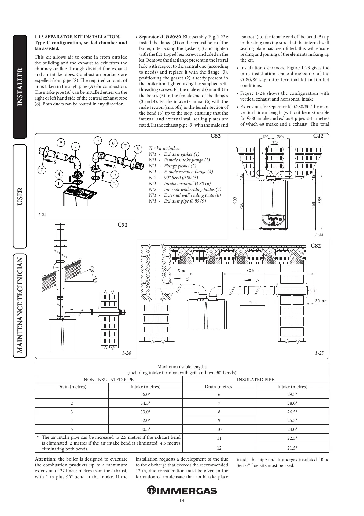
• Separator kit Ø 80/80. Kit assembly (Fig. 1-22):
install the ange (4) on the central hole of the
boiler, interposing the gasket (1) and tighten
with the at-tipped hex screws included in the
kit. Remove the at ange present in the lateral
hole with respect to the central one (according
to needs) and replace it with the ange (3),
positioning the gasket (2) already present in
the boiler and tighten using the supplied self-
threading screws. Fit the male end (smooth) to
the bends (5) in the female end of the anges
(3 and 4). Fit the intake terminal (6) with the
male section (smooth) in the female section of
the bend (5) up to the stop, ensuring that the
internal and external wall sealing plates are
tted. Fit the exhaust pipe (9) with the male end
(smooth) to the female end of the bend (5) up
to the stop; making sure that the internal wall
sealing plate has been tted, this will ensure
sealing and joining of the elements making up
the kit.
• Installation clearances. Figure 1-23 gives the
min. installation space dimensions of the
Ø 80/80 separator terminal kit in limited
conditions.
• Figure 1-24 shows the configuration with
vertical exhaust and horizontal intake.
• Extensions for separator kit Ø 80/80. e max.
vertical linear length (without bends) usable
for Ø 80 intake and exhaust pipes is 41 metres
of which 40 intake and 1 exhaust. is total
e kit includes:
N°1 - Exhaust gasket (1)
N°1 - Female intake ange (3)
N°1 - Flange gasket (2)
N°1 - Female exhaust ange (4)
N°2 - 90° bend Ø 80 (5)
N°1 - Intake terminal Ø 80 (6)
N°2 - Internal wall sealing plates (7)
N°1 - External wall sealing plate (8)
N°1 - Exhaust pipe Ø 80 (9)
Maximum usable lengths
(including intake terminal with grill and two 90° bends)
NON-INSULATED PIPE INSULATED PIPE
Drain (metres) Intake (metres) Drain (metres) Intake (metres)
1 36.0* 6 29.5*
2 34.5* 7 28.0*
3 33.0* 8 26.5*
4 32.0* 9 25.5*
5 30.5* 10 24.0*
* e air intake pipe can be increased to 2.5 metres if the exhaust bend
is eliminated, 2 metres if the air intake bend is eliminated, 4.5 metres
eliminating both bends.
11 22.5*
12 21.5*
Attention: the boiler is designed to evacuate
the combustion products up to a maximum
extension of 27 linear metres from the exhaust,
with 1 m plus 90° bend at the intake. If the
installation requests a development of the ue
to the discharge that exceeds the recommended
12 m, due consideration must be given to the
formation of condensate that could take place
inside the pipe and Immergas insulated “Blue
Series” ue kits must be used.