9
1-7
2
1
1-8
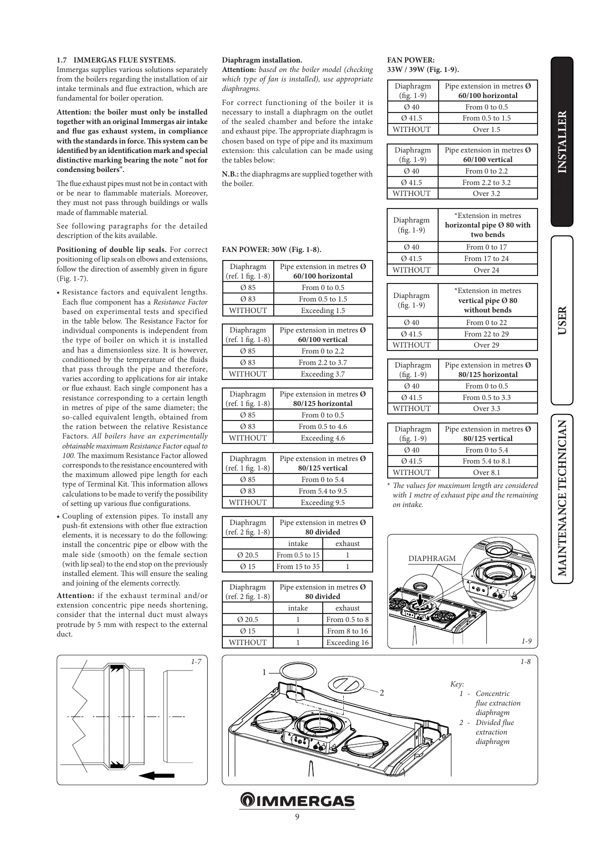
1-9
INSTALLERUSER
MAINTENANCE TECHNICIAN
1.7 IMMERGAS FLUE SYSTEMS.
Immergas supplies various solutions separately
from the boilers regarding the installation of air
intake terminals and ue extraction, which are
fundamental for boiler operation.
Attention: the boiler must only be installed
together with an original Immergas air intake
and ue gas exhaust system, in compliance
with the standards in force. is system can be
identied by an identication mark and special
distinctive marking bearing the note " not for
condensing boilers".
e ue exhaust pipes must not be in contact with
or be near to ammable materials. Moreover,
they must not pass through buildings or walls
made of ammable material.
See following paragraphs for the detailed
description of the kits available.
Positioning of double lip seals. For correct
positioning of lip seals on elbows and extensions,
follow the direction of assembly given in gure
(Fig. 1-7).
• Resistance factors and equivalent lengths.
Each ue component has a Resistance Factor
based on experimental tests and specified
in the table below. e Resistance Factor for
individual components is independent from
the type of boiler on which it is installed
and has a dimensionless size. It is however,
conditioned by the temperature of the uids
that pass through the pipe and therefore,
varies according to applications for air intake
or ue exhaust. Each single component has a
resistance corresponding to a certain length
in metres of pipe of the same diameter; the
so-called equivalent length, obtained from
the ration between the relative Resistance
Factors. All boilers have an experimentally
obtainable maximum Resistance Factor equal to
100. e maximum Resistance Factor allowed
corresponds to the resistance encountered with
the maximum allowed pipe length for each
type of Terminal Kit. is information allows
calculations to be made to verify the possibility
of setting up various ue congurations.
• Coupling of extension pipes. To install any
push-t extensions with other ue extraction
elements, it is necessary to do the following:
install the concentric pipe or elbow with the
male side (smooth) on the female section
(with lip seal) to the end stop on the previously
installed element. is will ensure the sealing
and joining of the elements correctly.
Attention: if the exhaust terminal and/or
extension concentric pipe needs shortening,
consider that the internal duct must always
protrude by 5 mm with respect to the external
duct.
Diaphragm installation.
Attention: based on the boiler model (checking
which type of fan is installed), use appropriate
diaphragms.
For correct functioning of the boiler it is
necessary to install a diaphragm on the outlet
of the sealed chamber and before the intake
and exhaust pipe. e appropriate diaphragm is
chosen based on type of pipe and its maximum
extension: this calculation can be made using
the tables below:
N.B.: the diaphragms are supplied together with
the boiler.
Key:
1 - Concentric
ue extraction
diaphragm
2 - Divided ue
extraction
diaphragm
Diaphragm
(ref. 1 g. 1-8)
Pipe extension in metres Ø
60/100 horizontal
Ø 85 From 0 to 0.5
Ø 83 From 0.5 to 1.5
WITHOUT Exceeding 1.5
Diaphragm
(ref. 1 g. 1-8)
Pipe extension in metres Ø
60/100 vertical
Ø 85 From 0 to 2.2
Ø 83 From 2.2 to 3.7
WITHOUT Exceeding 3.7
Diaphragm
(ref. 1 g. 1-8)
Pipe extension in metres Ø
80/125 horizontal
Ø 85 From 0 to 0.5
Ø 83 From 0.5 to 4.6
WITHOUT Exceeding 4.6
Diaphragm
(ref. 1 g. 1-8)
Pipe extension in metres Ø
80/125 vertical
Ø 85 From 0 to 5.4
Ø 83 From 5.4 to 9.5
WITHOUT Exceeding 9.5
Diaphragm
(ref. 2 g. 1-8)
Pipe extension in metres Ø
80 divided
intake exhaust
Ø 20.5
From 0.5 to 15
1
Ø 15
From 15 to 35
1
Diaphragm
(ref. 2 g. 1-8)
Pipe extension in metres Ø
80 divided
intake exhaust
Ø 20.5 1 From 0.5 to 8
Ø 15 1 From 8 to 16
WITHOUT 1 Exceeding 16
Diaphragm
(g. 1-9)
Pipe extension in metres Ø
60/100 horizontal
Ø 40 From 0 to 0.5
Ø 41.5 From 0.5 to 1.5
WITHOUT Over 1.5
Diaphragm
(g. 1-9)
Pipe extension in metres Ø
60/100 vertical
Ø 40 From 0 to 2.2
Ø 41.5 From 2.2 to 3.2
WITHOUT Over 3.2
Diaphragm
(g. 1-9)
*Extension in metres
horizontal pipe Ø 80 with
two bends
Ø 40 From 0 to 17
Ø 41.5 From 17 to 24
WITHOUT Over 24
Diaphragm
(g. 1-9)
*Extension in metres
vertical pipe Ø 80
without bends
Ø 40 From 0 to 22
Ø 41.5 From 22 to 29
WITHOUT Over 29
Diaphragm
(g. 1-9)
Pipe extension in metres Ø
80/125 horizontal
Ø 40 From 0 to 0.5
Ø 41.5 From 0.5 to 3.3
WITHOUT Over 3.3
Diaphragm
(g. 1-9)
Pipe extension in metres Ø
80/125 vertical
Ø 40 From 0 to 5.4
Ø 41.5 From 5.4 to 8.1
WITHOUT Over 8.1
DIAPHRAGM
* e values for maximum length are considered
with 1 metre of exhaust pipe and the remaining
on intake.
FAN POWER:
33W / 39W (Fig. 1-9).
FAN POWER: 30W (Fig. 1-8).