17
INSTALLER
USERMAINTENANCE TECHNICIAN
TECHNICAL DATA
1.11 IMMERGAS FLUE SYSTEMS
Immergas supplies various solutions separately from the boilers
regarding the installation of air intake terminals and ue exhaust,
which are fundamental for boiler operation.
e boiler must be installed with an original Immergas
“Green Range” inspectionable air intake system and vi-
sible ue gas extraction system made of plastic, with the
exception of the C6 conguration, as required by the re-
gulations in force and by the product’s approval. is
ue system can be identied by the specic identica-
tion mark bearing the following indication: “only for
condensation boilers”.
For non-original ue system, refer to the technical data
of the appliance.
e plastic pipes cannot be installed outdoors, for tracts
longer than 40 cm, without suitable protection from UV
rays and other atmospheric agents.
Resistance factors and equivalent lengths
Each ue component has a Resistance Factor based on experimen-
tal tests and specied in the table below.
e Resistance Factor for individual components is independent
from the type of boiler on which it is installed and has a dimen-
sionless size.
It is however, conditioned by the temperature of the uids that
pass through the pipe and therefore, varies according to applica-
tions for air intake or ue exhaust.
Each single component has a resistance corresponding to a cer-
tain length in metres of pipe of the same diameter; the so-called
equivalent length, can be obtained from the ratio between the re-
lative Resistance Factors.
All boilers have an experimentally obtainable maximum Resi-
stance Factor equal to 100.
e maximum Resistance Factor allowed corresponds to the resi-
stance encountered with the maximum allowed pipe length for
each type of Terminal Kit.
is information allows calculations to be made to verify the pos-
sibility of setting up various ue congurations.
To dimension the ue ducting using commercial com-
ponents, refer to the table of combustion parameters
(Par. 4.2).
A
B
10
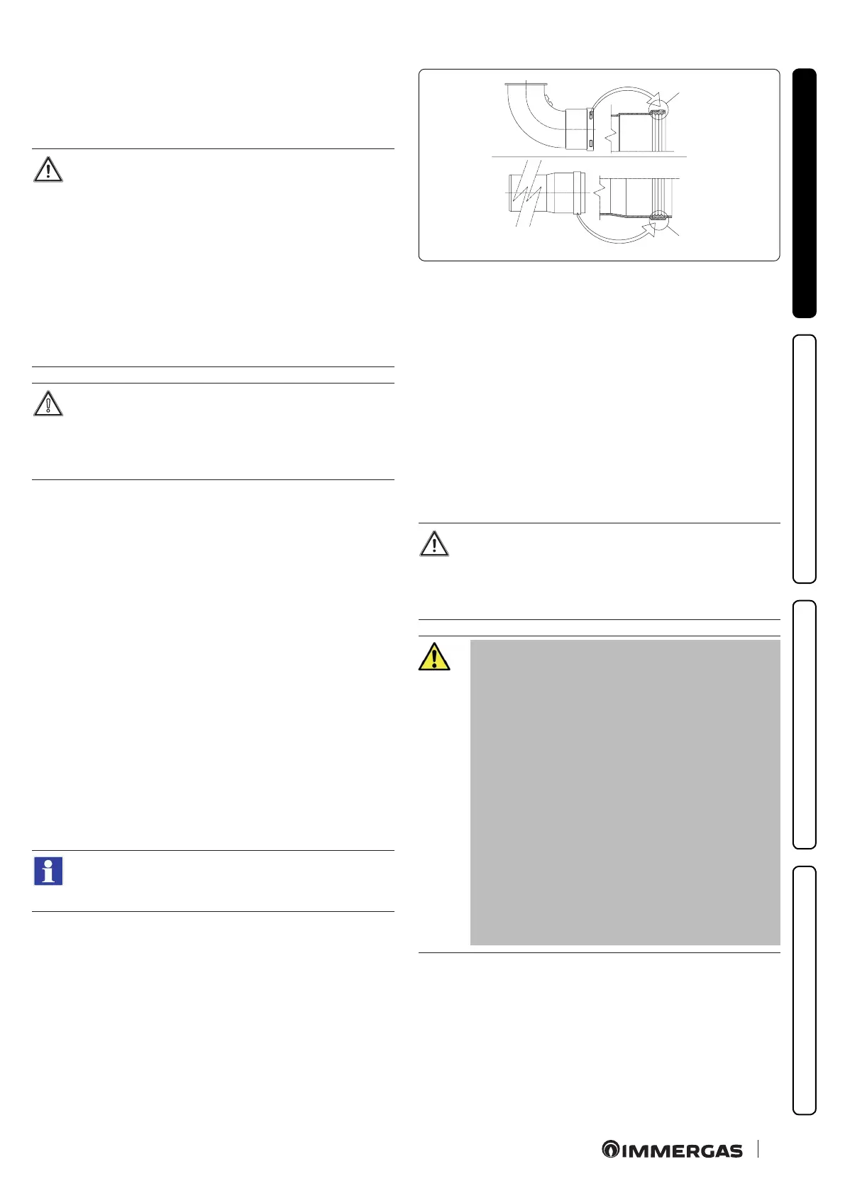
Positioning the gaskets (black) for “green range” ue systems.
Position the gasket correctly (for bends and extensions) (Fig. 10):
- gasket (A) with notches, to use for bends;
- gasket (B) without notches, to use for extensions.
If necessary, to ease the push-tting, spread the elements with
commonly-used talc.
Extension pipes and concentric elbows push-ttings.
To install push-tting extensions with other elements of the ue,
proceed as follows:
- Install the concentric pipe or elbow with the male side (smooth)
on the female side (with lip seal) to the end stop on the previou-
sly installed element in order to ensure sealing eciency of the
coupling.
If the exhaust terminal and/or extension concentric pipe
needs shortening, consider that the internal duct must
always protrude by 5 mm with respect to the external
duct.
For safety purposes, do not obstruct the
boiler intake/exhaust terminal, even
temporarily.
e various parts of the ue system must
be checked to ensure that they have been
laid in such a way as to prevent the cou-
pled parts from detaching, in particular,
the ue exhaust duct in the Ø80 separa-
tor kit conguration. If the condition de-
scribed above is not adequately guaran-
teed, it will be necessary to use the
appropriate retaining clamp kit.