50
INSTALLER
USERMAINTENANCE TECHNICIAN
TECHNICAL DATA
3.7 CONVERTING THE BOILER TO OTHER
TYPES OF GAS.
e gas conversion operation must be carried out by an
authorised company (e.g. Authorised Technical Assi-
stance Service).
If the appliance needs to be converted to a dierent gas type to that
specied on the data plate, request the relative conversion kit for
quick and easy conversion.
To convert to another type of gas the following operations are re-
quired:
- disconnect power to the appliance;
- replace the main burner injectors, making sure to insert the
special seal rings supplied in the kit, between the gas manifold
and the injectors;
- re-power the appliance;
- select, using the boiler keyboard, the gas parameter type (P01)
and select (nG) in the case of methane supply or (LG) in the case
of LPG supply and save it;
- Carry out complete calibration of the gas valve:
• adjust the boiler nominal heat output;
• adjust the boiler nominal heat output in domestic hot water
phase;
- adjust (if necessary) the minimum heat output of the boiler in
the heating phase (Parag. 3.9parameter P05);
- adjust (eventually) the maximum heating power (Parag. 3.9paj-
rameter P06);
- aer completing the conversion, apply the sticker, contained in
the conversion kit, near the data nameplate. Using an indelible
marker pen, delete the data relative to the old type of gas.
ese adjustments must be made with reference to the type of gas
used, following the indications given in the table (Par. 4.1).
Checks following conversion to another type of gas.
Aer having made sure that the conversion is complete and that
the calibration has been successful, you must make sure that:
- there is no ame in the combustion chamber;
- the burner ame is not too high or low and that it is stable (does
not detach from burner);
e pressure testers used for calibration
should be perfectly closed and there
should be no leaks from the gas circuit.
Maintenance operations must be carried out by an au-
thorised company (e.g. Authorised Technical Assistan-
ce Service).
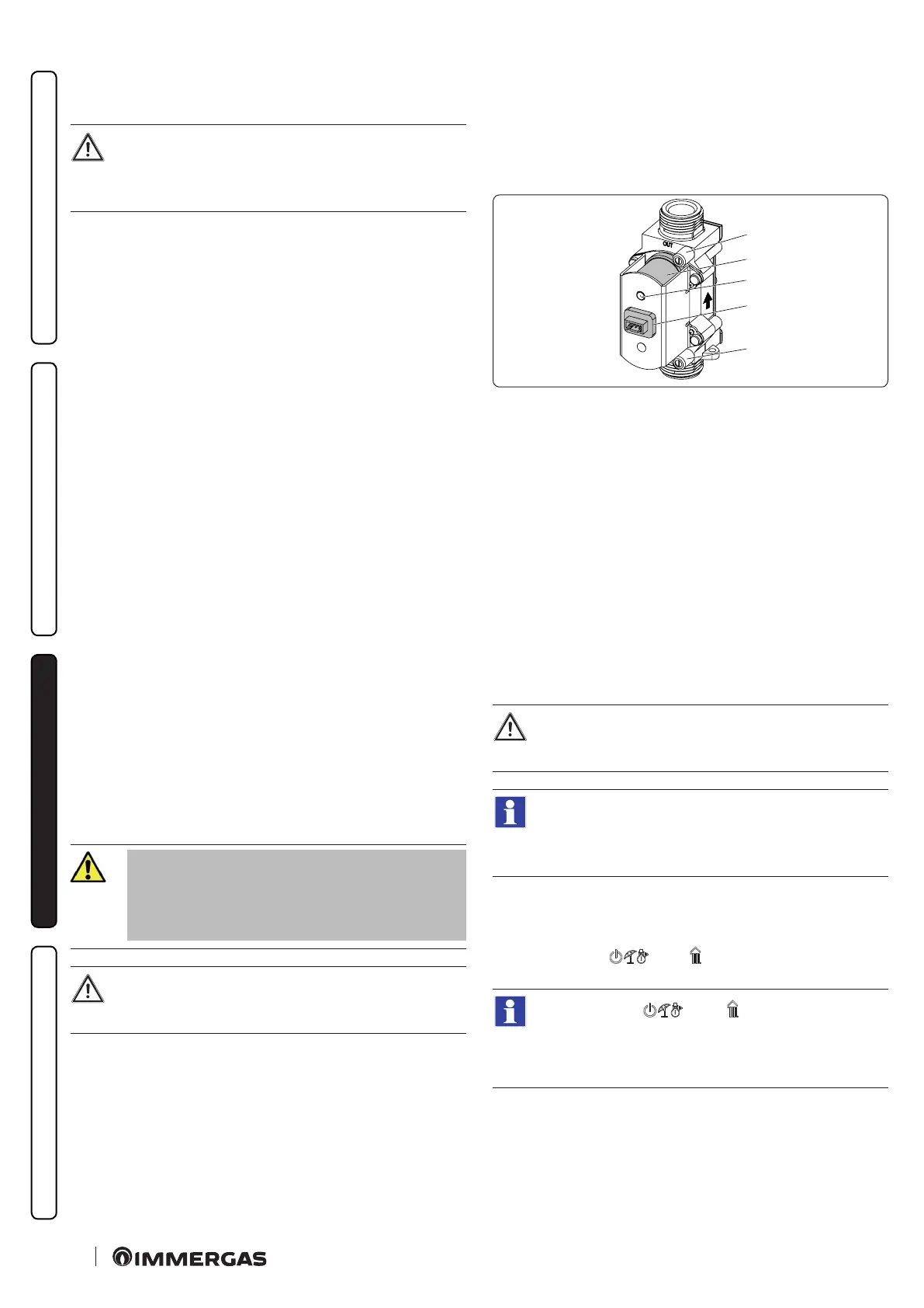
Burner adjustment must be carried out using a dierential "U" or
digital type pressure gauge connected to the pressure socket loca-
ted above the sealed chamber (det. 14 Fig. 35) and the gas valve
pressure point (det. 1 Fig. 39), keeping to the pressure value given
in the table (Par. 4.1) according to the type of gas for which the
boiler is prepared.
1
4
3
2
5
39
Key (Fig. 39):
1 - Gas valve outlet pressure point
2 - Coil
3 - Wiring connector
4 - Gas valve inlet pressure point
5 - P. Ref.
3.8 GAS VALVE CALIBRATION
e valve calibration must be carried out when the gas valve or the
P.C.B. is replaced or in the case of conversion to a dierent type of
gas.
To access the calibration phase, proceed as described below (Pa-
rag. 2.3):
Complete calibration
Before carrying out complete calibration, ensure that all
the requirements indicated in parag. 1.23 - 1.24.
No active requests for central heating or D.H.W. pro-
duction must be present and the boiler must not be in
“Stand-by” mode.
Access the valve calibration function.
Set parameter P15 to 5 and exit from the menu.
- Adjustment of boiler nominal thermal heat output.
• Press buttons ( ) and ( ) simultaneously for 5 seconds
until "Au" + "to" appears alternately on the display;
Press buttons ( ) and ( ) again for 5 seconds or
wait 2 minutes without implementing any adjustment to
exit from the complete calibration phase.
 Loading...