47
INSTALLER
USERMAINTENANCE TECHNICIAN
TECHNICAL DATA
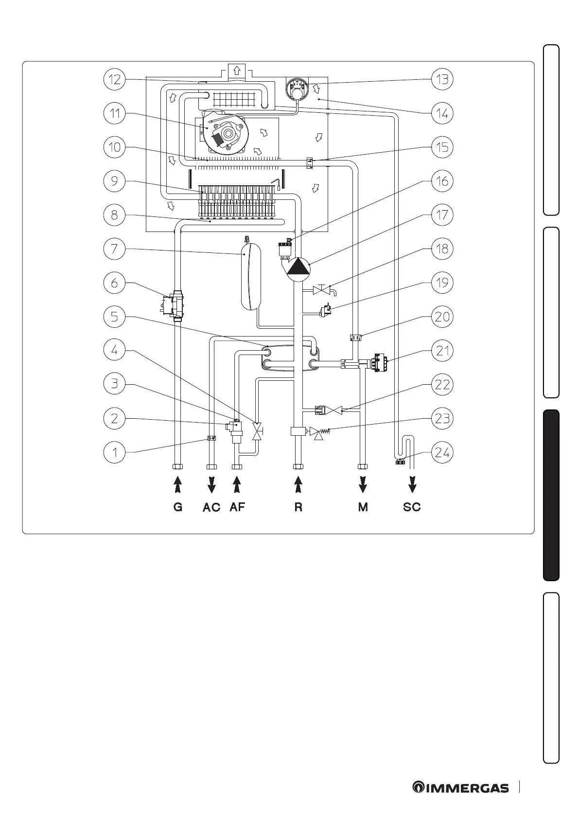
3.4 HYDRAULIC DIAGRAM
37
Key (Fig. 37):
1 - DHW probe
2 - D.H.W. ow switch
3 - Flow limiter
4 - System lling valve
5 - DHW heat exchanger
6 - Gas valve
7 - System expansion vessel
8 - Gas manifold
9 - Burner
10 - Primary heat exchanger
11 - Fan
12 - Condensing heat exchanger
13 - Flue pressure switch
14 - Sealed chamber
15 - Flow probe
16 - Air vent valve
17 - Boiler pump
18 - System draining valve
19 - System pressure switch
20 - Safety thermostat
21 - Motorized 3-way valve
22 - By-pass
23 - 3 bar safety valve
24 - Condensate drain trap
G - Gas supply
AC - Domestic hot water outlet
AF - Domestic hot water inlet
R - System return
M - System ow
SC - Condensate drain