Remote Friend Control or Room ermostat:
the boiler is arranged for application of a Room ermostat
(TA) or Remote Friend Control (CAR). Connect the Room
ermostat to terminals 40 and 41 and remove jumper X20.
e Remote Friend Control must be connected to terminals
42 and 43 on the electronic card, respecting the polarity and
removing jumper X20.
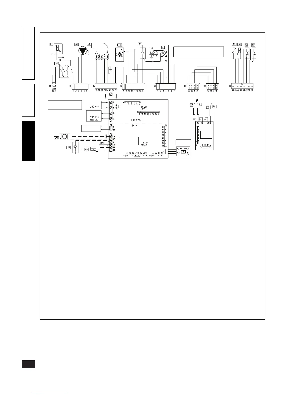
3.2 Wiring diagram - Victrix 27.
Key:
B1 - Heating NTC sensor
B2 - Domestic circuit NTC sensor
B3 - External sensor (optional)
CAR - Remote Friend Control (optional)
DL1 - Heating On LED
DL2 - Domestic circuit On LED
DL3 - Flame presence LED
E1-E2 - Igniters
E3 - Detection plug
E4 - Temperature safety thermostat
M1 - Circulating pump
M2 - Fan
PU1 - “Block” reset
R2 - Domestic circuit thermal ywheel PTC
S1 - Main rotary switch
S2 - Pump ow switch microswitch
S3 - Domestic circuit priority microswitch
T1 - Voltage transformer
TA - Room thermostat On/O (optional)
U1 - Rectier inside gas valve connector (present on Honeywell and Dungs)
X20 - Room thermostat or Remote Friend Control inhibitor jumper
Y1 - Gas valve
white
white
white
white
red
gey-green
pink
pink
pink
purple
purple
purple
red
red
red
white
white
red
grey
grey
brown
orange
brown
brown
brown
white-blue
white-blue
brown
red-black brown
blue
black
black
black
red-black
red-black
red-black
black
black
grey
grey
red
orange
orange
orange
blue
blue
blue
blue
N.B.
The rectifier U1 is present on boilers equipped
with Honeywell and Dungs gas valve
N.B.
The connectors edged in black
are inserted on the ignition unit.
ADJUSTMENT
CARD
IGNITION/
DETECTION
UNIT
DISPLAY CARD
Zone unit
(optional)
Auxiliary
output
Power supply