1.5 Air intake and fume exhaust terminal installation.
Immergas supplies various solutions separately from the
boilers for the installation of air intake and fume exhaust
terminals necessary for boiler operation.
Important: the boiler must only be installed together with
an original Immergas “Green Range” air intake and fume
extraction system in plastic, as required by current regula-
tions. is system is identiable by a special distinctive
marking giving the note: “for condensing boilers only”.
Important:
- for C1 type installation with doubled terminals, these must
be installed inside a 50 cm square perimeter;
- for C3 type installation the terminals must be installed
inside a 50 cm square perimeter and the distance between
the two levels of the openings must be less than 50 cm;
- for C5 type installation the two terminals must not be
installed on opposite walls of the building.
• Resistance factors and equivalent lengths. Each fume ex-
traction system component has a resistance factor obtained
from preliminary tests and specied in the table below. e
resistance factor of the single component does not depend
on the type of boiler on which it is installed and is a dimen-
sional value. It is based on the temperature of uids passing
through the ducts and therefore varies according to use in
air intake or fume exhaust. Each single component has a
resistance corresponding to a certain length in metres of
pipe of the same diameter: the so-called equivalent length.
All boilers have an experimentally obtainable maximum
Resistance Factor equal to 100. e maximum permissible
resistance factor corresponds to the resistance detected with
the maximum permissible pipe length with each type of
Terminal Kit. is information enables calculations for
verifying the possibility of executing a wide range of fume
extraction system congurations.
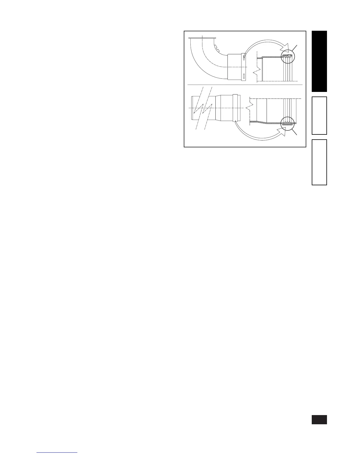
Positioning of seals (black) for “Green Range” fume ex-
traction system. Make sure to correctly place the seal (for
bends or extensions) as shown in the gure:
- seal (A) with notches, to be used for bends;
- seal (B) without notches, to be used for extensions;
N.B.: if the lubrication of the components (already carried
out by the manufacturer) is insucient, remove the residual
lubricant using a dry rag, then cover the parts with normal
or industrial talc to facilitate coupling.
(A)
(B)