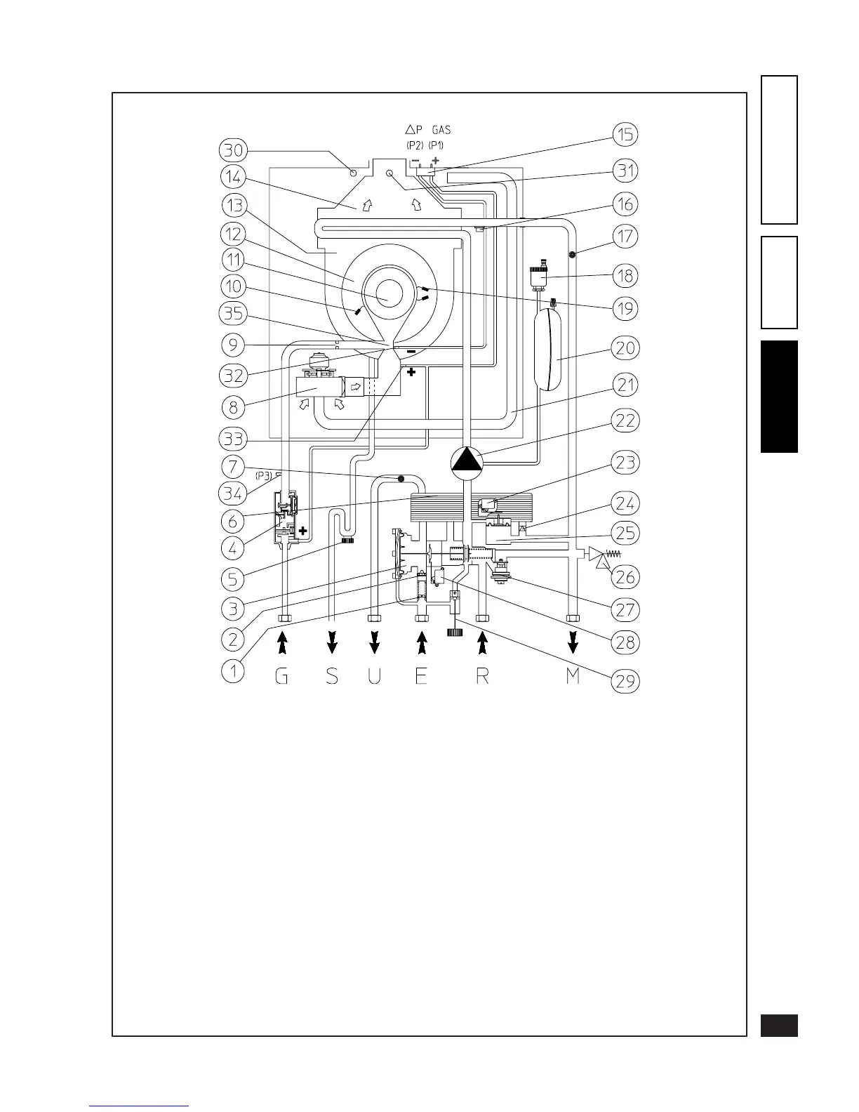
3.3 Plumbing diagram - Victrix 20.
Key:
1 - Minimum owrate valve
2 - Flow limiter
3 - 3-way hydraulic valve
4 - Gas valve
5 - Condensate trap
6 - Domestic water heat exchanger
7 - Domestic circuit adjustment NTC sensor
8 - Air fan
9 - Gas nozzle
10 - Igniter sensor
11 - Burner
12 - Condensing module cover
13 - Condensing module
14 - Fume extractor hood
15 - p gas pressure point
16 - NTC limit and heating control sensor
17 - Overtemperature safety thermostat
18 - Automatic air valve
19 - Igniters
20 - Expansion tank
21 - Air intake pipe
22 - Circulating pump
23 - Circulating pump pressure switch microswitch
24 - One-way valve
25 - Circulating pump pressure switch
26 - 3 bar safety valve
27 - Automatic by-pass
28 - Domestic circuit ow switch microswitch
29 - Filler cock
30 - Air analyzer chamber
31 - Fume analyzer chamber
32 - Venturi negative signal (P2)
33 - Venturi positive signal (P1)
34 - Gas valve outlet pressure point (P3)
35 - Air/gas Venturi manifold
G - Gas supply
S - Condensate drain
U - Hot domestic water outlet
E - Domestic water inlet
R - System return
M - System delivery