12
1-11
1-9
1-10
12
INSTALLERUSER
MAINTENANCE TECHNICIAN
1.12 OUTDOOR INSTALLATION IN A
PARTIALLY PROTECTED AREA.
N.B.: a partially protected area is one in which the
appliance is not exposed to the direct action of the
weather (rain, snow, hail, etc..).
NOTE: this type of installation is only possible
when permitted by the laws in force in the ap-
pliance’s country of destination.
• Conguration type B, open chamber and
forced draught.
Using the special coverage kit one can achieve
direct air intake (Fig. 1-9) and fumes exhaust in
a single ue or directly outside. In this congura-
tion it is possible to install the boiler in a partially
protected place. In this conguration the boiler
is classied as type B
23
.
With this conguration:
- air intake takes place directly from the envi-
ronment in which the appliance is installed
(outside);
- the fumes exhaust must be connected to its own
single ue (B
23
) or ducted directly outside via a
vertical terminal for direct exhaust (B
53
) or via
an Immergas ducting system (B
53
).
The technical regulations in force must be
respected.
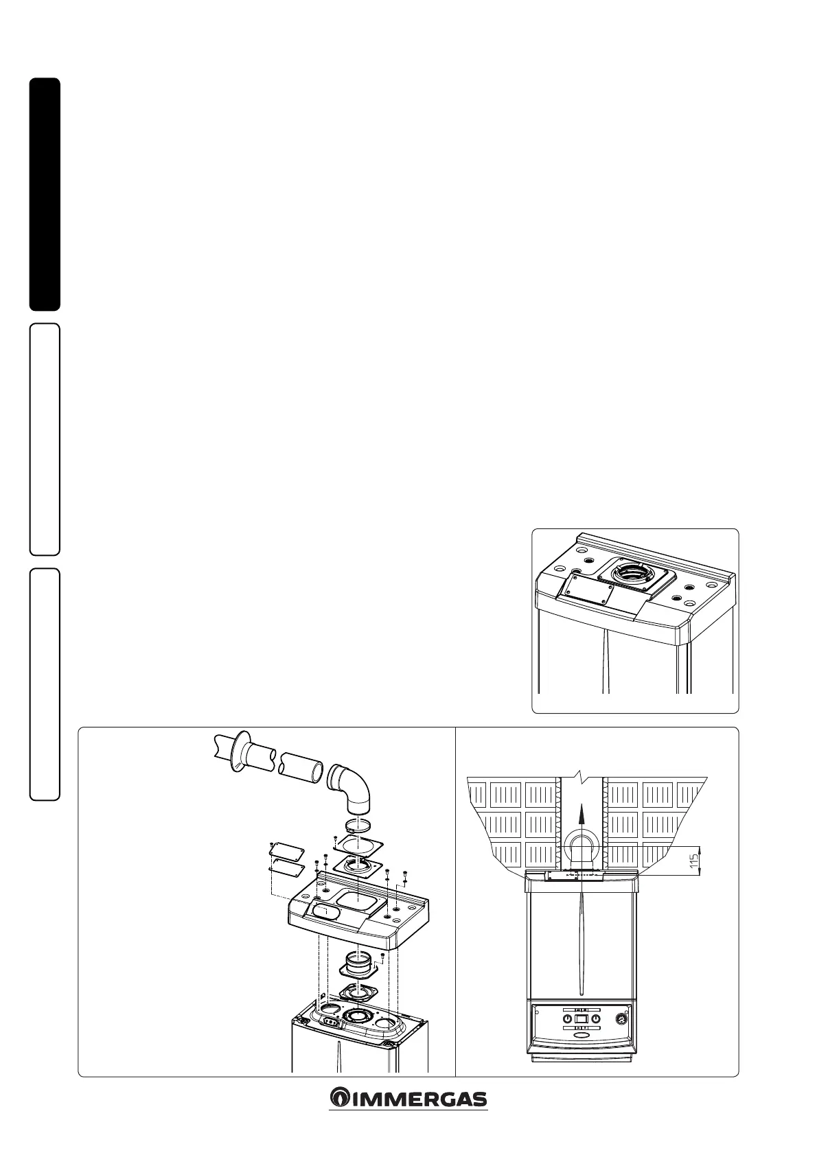
• Coverage kit assembly (Fig. 1-10). Remove
the two plugs and the gaskets present from
the two lateral holes with respect to the central
one. Now cover the right intake hole using the
relevant plate, xing it onto the le side using
the 2 previously-removed screws. Install the
Ø 80 outlet ange on the central hole of the
boiler, taking care to insert the gasket supplied
with the kit and tighten by means of the screws
provided. Install the upper cover, xing it using
the 4 screws present in the kit, positioning the
relevant gaskets. Engage the 90° Ø 80 bend
with the male end (smooth) in the female end
(with lip seal) of the Ø 80 ange unit until it
stops. Introduce the gasket, making it run along
the bend. Fix it using the sheet steel plate and
tighten by means of the straps present in the
kit, making sure to block the 4 gasket aps. Fit
the male end (smooth) of the exhaust terminal
into the the female end of the bend 90° Ø 80,
making sure that the relevant wall sealing
plate is already tted; this will ensure hold and
joining of the elements making up the kit.
Max. length of exhaust duct. e ue pipe (both
vertical or horizontal) can be extended to a max.
length of 30 linear metres.
• Coupling of extension pipes. To install push-t-
ting extensions with other elements of the ue,
proceed as follows: Couple the pipe or elbow
with the male side (smooth) in the female side
(with lip seal) to the end stop on the previously
installed element. This will ensure sealing
eciency of the coupling.
• Conguration without cover kit in a partially
protected location (type C boiler)
By leaving the side plugs tted it is possible
to install the appliance externally without the
cover kit. Installation takes place using the
Ø60/100, Ø 80/125 and separator Ø 80/80
concentric intake/ exhaust kits. Refer to the
paragraph relative to indoor installation. In
this conguration the upper cover kit guaran-
tees additional protection for the boiler. It is
recommended but not compulsory.
e cover kit includes:
N° 1 ermoformed cover
N°1 Gasket clamping plate
N°1 Gasket
N°1 Gasket tightening strap
N°1 Intake hole covering plate
e terminal kit includes:
N° 1 Gasket
N° 1 Discharge ange Ø 80
N° 1 Bend 90° Ø 80
N° 1 Drain pipe Ø 80
N° 1 Wall sealing plate

 Loading...