16
1
2
3
3
3
4
5
6
7
6
8
9
A
10
11
12
12
1-24
1-23
A
B
A
C
16
INSTALLERUSER
MAINTENANCE TECHNICIAN
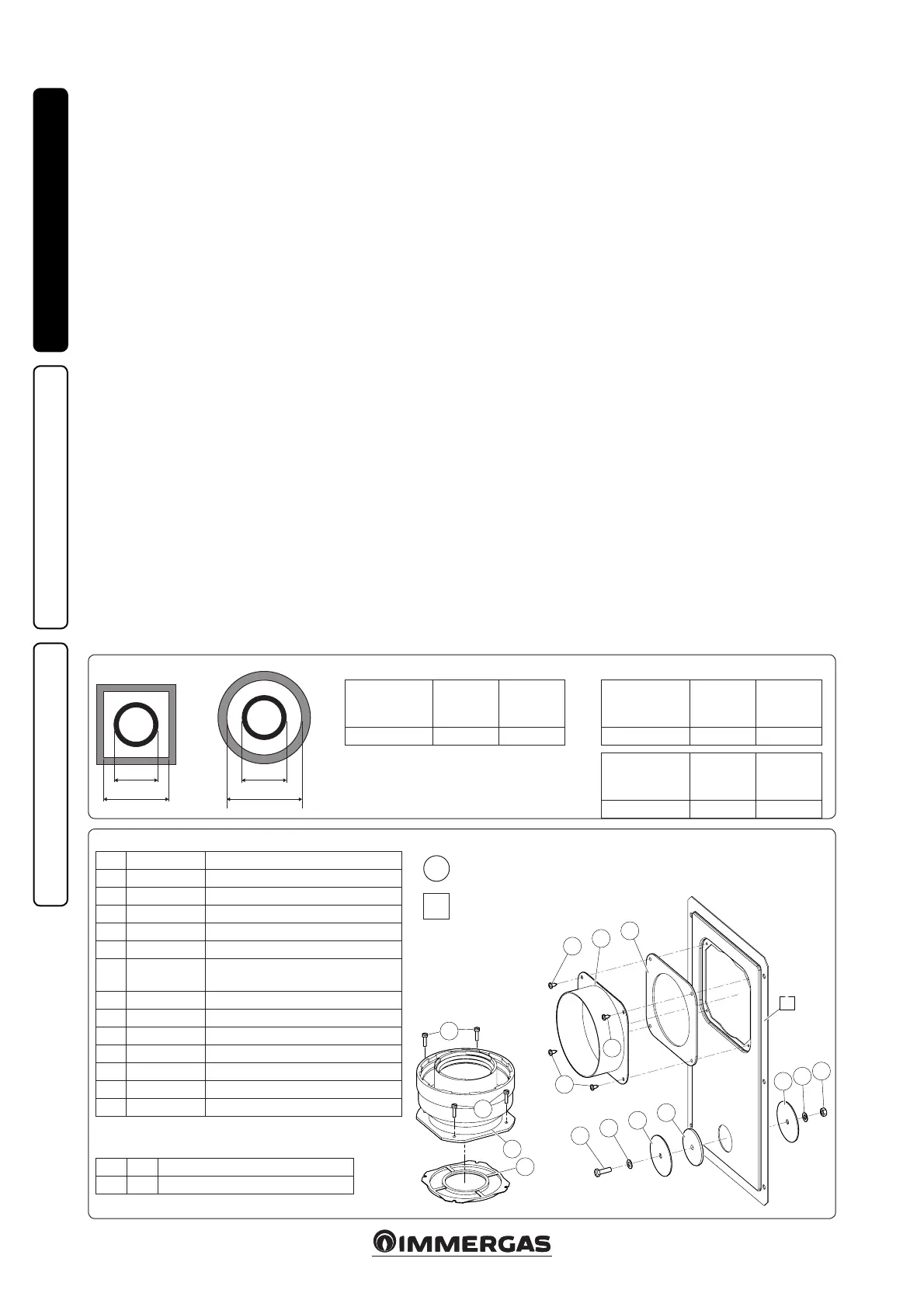
Kit composition:
Ref. Qty Description
1 1 Door adaptor Ø 100 or Ø 125
2 1 Door gasket made of neoprene
3 4 Screws 4.2 x 9 AF
4 1 Hex headed screw M6 x 20
5 1 Flat nylon washer M6
6 2 Door hole closure metal-sheet plate
plug
7 1 Plug gasket made of neoprene
8 1 Toothed washer M6
9 1 Nut M6
10 1 (kit 80/125) Concentric gasket Ø 60-100
11 1 (kit 80/125) Flanged adapter Ø 80-125)
12 4 (kit 80/125) Hex headed screws M4 x 16 slotted
- 1 (kit 80/125) Bag of lubricating talc
Installation drawings key:
Unique identication of the component in
the kit
Identication of the component not supplied
in this kit
1
A
Supplied separately:
Ref. Qty Description
A 1 Ducting kit door
Rigid Ø 80
ducting (A)
mm
SHAFT
(B) mm
SHAFT
(C) mm
86 126 146
Flexible Ø 80
ducting (A)
mm
SHAFT
(B) mm
SHAFT
(C) mm
90 130 150
Rigid Ø 60
ducting (A)
mm
SHAFT
(B) mm
SHAFT
(C) mm
66 106 126
1.16 ADAPTOR C9 KIT INSTALLATION.
is kit allows to install an Immergas boiler in
conguration "C
93
", achieving the combustion air
intake directly from the sha featuring the fumes
exhaust, obtained by means of a ducting system.
System composition.
e system must be combined with the following
components (sold separately) to be functional
and complete:
- kit C
93
version Ø 100 or Ø125
- ducting kit Ø 60 or Ø 80
- fumes exhaust kit Ø 60/100 or Ø 80/125 con-
gured according to the installation and type
of boiler.
Kit Assembly.
- Mount the components of kit "C9" on the door
(A) of the ducting system (Fig. 1-24).
- (Version Ø 125 only) mount the anged adap-
tor (11) interposing the concentric gasket (10)
on the boiler, tting it with the screws (12).
- Mount the ducting system as described in the
relative instructions sheet.
- Calculate the distances between the boiler drain
and the bend of the ducting system.
- Prepare the boiler ue system, making sure that
the internal pipe of the concentric kit is tted
properly in the bend of the ducting system
(quota "X" g. 1-25), while the external pipe
must be tted on the adaptor until it stops (1).
N.B.: to encourage the removal of possible
condensate forming in the exhaust pipe, tilt
the pipes towards the boiler with a minimum
slope of 1.5%.
- Mount the cover (A) complete with adaptor (1)
and caps (6) on the wall and assemble the ue
system to the ducting system.
N.B.: (version Ø 125 only) before assembly check
the gaskets are in the right position. In the event
component lubrication (already carried out
by the manufacturer) is not sucient, remove
the residual lubricant using a dry cloth, then
to ease tting coat the parts with common or
industrial talc.
Once all components have been assembled prop-
erly, the exhaust fumes will be expelled via the
ducting system; the combustion air for normal
boiler operation will be aspirated directly by the
sha (Fig. 1-25).
Technical data.
- e dimensions of the shas must ensure a
minimum gap between the outer wall of the
smoke duct and the inner wall of the sha: 30
mm for circular section shas and 20 mm in
the event of a square section sha (Fig. 1-23).
- Maximum 2 changes of direction are allowed
on the vertical section of the ue system with
a maximum clearance angle of 30° with respect
to the vertical.
- e maximum vertical extension using a Ø
60 ducting system is 13 m, the maximum
extension includes 1 bend Ø 60/10 at 90°, 1 m
of horizontal pipe 60/100, 1 90° ducted bend
Ø 60 and the roof terminal for ducting.
To determine the C
93
ue system in congu-
rations other than that described (Fig. 1-25)
one must consider that 1 metre of ducted pipe
according to the indications described has a
resistance factor equal to 4.9.
- e maximum vertical extension using a Ø 80
ducting system is 28 m, the maximum exten-
sion includes 1 adapter 60/100 to 80/125, 1 87°
bend Ø 80/125, 1 m of horizontal pipe 80/125,
1 90° ducted bend Ø 80 and the roof terminal
for ducting.
To determine the C
93
ue system in congura-
tions other than that described (Fig. 1-25) one
must consider the following pressure drops:
- 1 m of concentric pipe Ø 80/125 = 1 m of
ducted pipe;
- 1 87° bend = 1.4 m of ducted pipe;
Consequently one must subtract the equivalent
length of the part added to the 28 m available.

 Loading...